LIGHTING (EXT) LIGHTING SYSTEM(w/ Headlight ECU) B2410 Headlight Swivel ECU LH Communication B2411 Headlight Swivel ECU RH Communication
DESCRIPTION
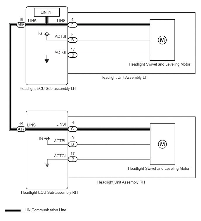
Each headlight ECU sub-assembly and headlight swivel and leveling motor communicate via LIN communication.
The headlight swivel and leveling motor operates according to power supplied and automatic headlight beam level control signals from its respective headlight ECU sub-assembly and sends its operating state to the headlight ECU sub-assembly.
| DTC No. | Detection Item | DTC Detection Condition | Trouble Area | DTC Output from |
|---|---|---|---|---|
| B2410 | Headlight Swivel ECU LH Communication | Malfunction in LIN communication error | ·
Headlight unit assembly LH ·
Headlight unit assembly RH ·
Harness or connector ·
Headlight ECU sub-assembly LH ·
Headlight ECU sub-assembly RH |
AFS |
| B2411 | Headlight Swivel ECU RH Communication | Malfunction in LIN communication error | ·
Headlight unit assembly RH ·
Headlight unit assembly LH ·
Harness or connector ·
Headlight ECU sub-assembly RH ·
Headlight ECU sub-assembly LH |
AFS |
WIRING DIAGRAM
CAUTION / NOTICE / HINT
- NOTICE:
-
If the headlight ECU sub-assembly LH has been replaced, it is necessary to synchronize the vehicle information and initialize the headlight ECU sub-assembly LH.
-
Click hereVehicle Exterior>LIGHTING (EXT)>LIGHTING SYSTEM (w/ Headlight ECU)>INITIALIZATION
PROCEDURE
Connect the GTS to the DLC3.
Turn the ignition switch on (IG).
Turn the GTS on.
Enter the following menus: Body Electrical / AFS / Clear DTCs.
Clear the DTCs.
- Body Electrical > AFS > Clear DTCs
- 50002 165
- Result:
Proceed to NEXT
NEXT
Connect the GTS to the DLC3.
Turn the ignition switch on (IG).
Wait 10 seconds or more.
Turn the GTS on.
Enter the following menus: Body Electrical / AFS / Trouble Codes.
Check for DTCs.
- Body Electrical > AFS > Trouble Codes
- 50001 165
- OK:
DTC B2410 and B2411 are not output.
- Result:
Result Proceed to OK A NG (DTC B2410 is output) B NG (DTC B2411 is output) C NG (DTC B2410 and B2411 are output) D
A
Click hereGeneral>INTRODUCTION>HOW TO TROUBLESHOOT ECU CONTROLLED SYSTEMS>HOW TO PROCEED WITH TROUBLESHOOTING
B
C
D
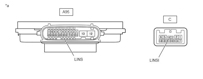
| *a | Component without harness connected
(Headlight ECU Sub-assembly LH) |
- | - |
Remove the headlight ECU sub-assembly LH.
Click hereVehicle Exterior>LIGHTING (EXT)>HEADLIGHT ECU>REMOVAL
Measure the resistance according to the value(s) in the table below.
- Standard Resistance:
Tester Connection Condition Specified Condition A95-19 (LINS) - C-4 (LINSI) Always Below 1 Ω
- Result:
Proceed to OK NG
OK
NG
Disconnect the A95 headlight ECU sub-assembly LH connector.
Disconnect the A17 headlight ECU sub-assembly RH connector.
Measure the resistance according to the value(s) in the table below.
- Standard Resistance:
Tester Connection Condition Specified Condition A95-19 (LINS) - A17-19 (LINS) Always Below 1 Ω
- Result:
Proceed to OK NG
OK
NG
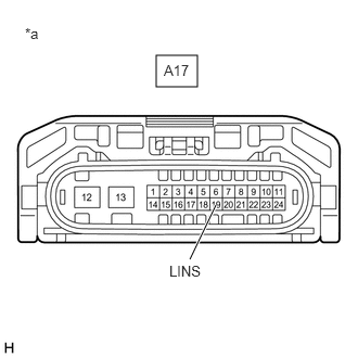
| *a | Front view of wire harness connector
(to Headlight ECU Sub-assembly RH) |
Disconnect the headlight ECU sub-assembly RH connector.
Using the GTS, check the waveform.
- OK:
Tester Connection Switch Condition Specified Condition A17-19 (LINS) - Body ground Ignition switch on (IG) Pulse generation
- Result:
Proceed to OK NG
OK
NG
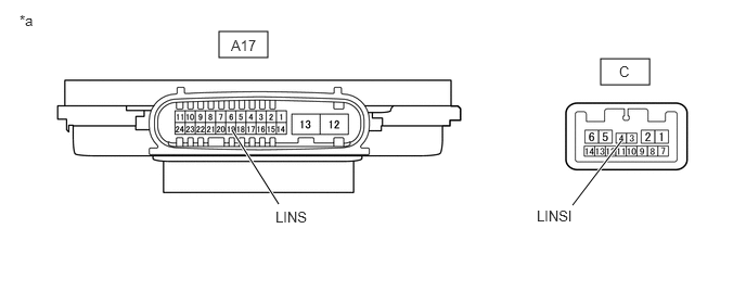
| *a | Component without harness connected
(Headlight ECU Sub-assembly RH) |
- | - |
Remove the headlight ECU sub-assembly RH.
Click hereVehicle Exterior>LIGHTING (EXT)>HEADLIGHT ECU>REMOVAL
Measure the resistance according to the value(s) in the table below.
- Standard Resistance:
Tester Connection Condition Specified Condition A17-19 (LINS) - C-4 (LINSI) Always Below 1 Ω
- Result:
Proceed to OK NG
OK
NG
Disconnect the A95 headlight ECU sub-assembly LH connector.
Disconnect the A17 headlight ECU sub-assembly RH connector.
Measure the resistance according to the value(s) in the table below.
- Standard Resistance:
Tester Connection Condition Specified Condition A95-19 (LINS) or A17-19 (LINS) - Body ground Always 10 kΩ or higher
- Result:
Proceed to OK NG
OK
NG
Connect the GTS to the DLC3.
Turn the ignition switch on (IG).
Turn the GTS on.
Enter the following menus: Body Electrical / AFS / Clear DTCs.
Clear the DTCs.
- Body Electrical > AFS > Clear DTCs
- 50002 165
- Result:
Proceed to NEXT
NEXT
Disconnect the A17 headlight ECU sub-assembly RH connector.
Connect the GTS to the DLC3.
Turn the ignition switch on (IG).
Wait 10 seconds or more.
Turn the GTS on.
Enter the following menus: Body Electrical / AFS / Trouble Codes.
Check for DTCs.
- Body Electrical > AFS > Trouble Codes
- 50001 165
- Result:
Result Proceed to DTC B2411 is output A DTC B2410 and B2411 are output B
A
B
Connect the GTS to the DLC3.
Turn the ignition switch on (IG).
Turn the GTS on.
Enter the following menus: Body Electrical / AFS / Clear DTCs.
Clear the DTCs.
- Body Electrical > AFS > Clear DTCs
- 50002 165
- Result:
Proceed to NEXT
NEXT
Remove the headlight ECU sub-assembly RH from headlight unit assembly RH.
Click hereVehicle Exterior>LIGHTING (EXT)>HEADLIGHT ECU>REMOVAL
Reconnect the A17 headlight ECU sub-assembly RH connector.
Connect the GTS to the DLC3.
Turn the ignition switch on (IG).
Wait 10 seconds or more.
Turn the GTS on.
Enter the following menus: Body Electrical / AFS / Trouble Codes.
Check for DTCs.
- Body Electrical > AFS > Trouble Codes
- 50001 165
- Result:
Result Proceed to DTC B2411 is output A DTC B2410 and B2411 are output B
A
B
Connect the GTS to the DLC3.
Turn the ignition switch on (IG).
Turn the GTS on.
Enter the following menus: Body Electrical / AFS / Clear DTCs.
Clear the DTCs.
- Body Electrical > AFS > Clear DTCs
- 50002 165
- Result:
Proceed to NEXT
NEXT
Remove the headlight ECU sub-assembly LH from headlight unit assembly LH.
Click hereVehicle Exterior>LIGHTING (EXT)>HEADLIGHT ECU>REMOVAL
Reconnect the A95 headlight ECU sub-assembly LH connector.
Connect the GTS to the DLC3.
Turn the ignition switch on (IG).
Wait 10 seconds or more.
Turn the GTS on.
Enter the following menus: Body Electrical / AFS / Trouble Codes.
Check for DTCs.
- Body Electrical > AFS > Trouble Codes
- 50001 165
- Result:
Result Proceed to DTC B2410 is output A DTC B2410 and B2411 are output B
A
B