CLUTCH CLUTCH PEDAL(for LHD) REMOVAL
CAUTION / NOTICE / HINT
The necessary procedures (adjustment, calibration, initialization, or registration) that must be performed after parts are removed, installed, or replaced during the clutch pedal support assembly removal/installation are shown below.
| Replacement Part or Procedure | Necessary Procedures | Effect/Inoperative Function When Necessary Procedures are not Performed | Link |
|---|---|---|---|
| Disconnect cable from negative battery terminal | Memorize steering angle neutral point | Panoramic view monitor system | ( ) |
- HINT:
-
When the cable is disconnected/reconnected to the auxiliary battery terminal, systems temporarily stop operating. However, each system has a function that completes learning the first time the system is used.
- ·
Learning completes when vehicle is driven
Effect/Inoperative Function When Necessary Procedures are not Performed Necessary Procedures Link *1: When performing learning using the GTS
Click here(
)
Lane tracing assist system Drive the vehicle straight ahead at 35 km/h (22 mph) or more for 5 second or more. ( )
Pre-collision system Simple intelligent parking assist system*1 Parking support brake system*1
·Learning completes when vehicle is operated normally
Effect/Inoperative Function When Necessary Procedures are not Performed Necessary Procedures Link Air conditioning system
·Back door opener
Perform door unlock operation with door control switch or electrical key transmitter sub-assembly switch. ( )
Air conditioning system After the ignition switch is turned to ON, the servo motor standard position is recognized. -
PROCEDURE

 1.REMOVE AIR CONDITIONER UNIT ASSEMBLY
for Denso Made:
Click hereVehicle Interior>HEATING / AIR CONDITIONING>AIR CONDITIONING UNIT (for DENSO Made)>REMOVAL
for Valeo Made:
Click hereVehicle Interior>HEATING / AIR CONDITIONING>AIR CONDITIONING UNIT (for VALEO Made)>REMOVAL
31410
2.DISCONNECT CLUTCH MASTER CYLINDER ASSEMBLY
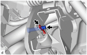
Remove the clip from the clevis pin.
Remove the clevis pin and disconnect the clutch master cylinder assembly from the clutch pedal sub-assembly.
3.REMOVE CLUTCH PEDAL SUPPORT ASSEMBLY
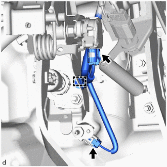
Disconnect the 2 connectors.
Disengage the clamp from the clutch pedal support assembly.
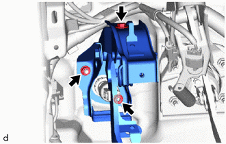
Remove the bolt and No. 4 instrument panel bracket from the clutch pedal support assembly.
Remove the 2 nuts and clutch pedal support assembly from the clutch master cylinder assembly.
88280A
4.REMOVE CLUTCH SWITCH ASSEMBLY
89280
5.REMOVE CLUTCH PEDAL STROKE SENSOR ASSEMBLY
31301A
6.REMOVE CLUTCH PEDAL SPRING
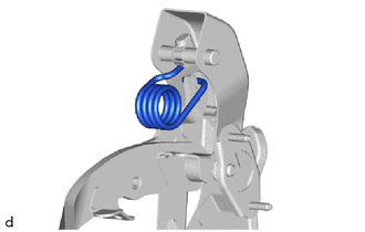
Move the pedal to the full stroke position and remove the clutch pedal spring.
31301
7.REMOVE CLUTCH PEDAL SUB-ASSEMBLY
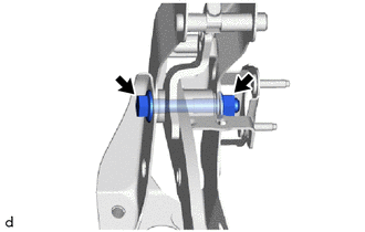
Remove the bolt, nut, clutch pedal sub-assembly and clutch pedal bracket sub-assembly from the clutch pedal support sub-assembly.
31353
8.REMOVE CLUTCH PEDAL SPRING HOLDER
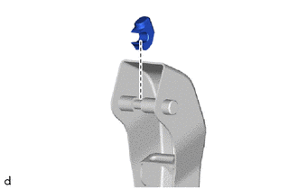
Remove the clutch pedal spring holder from the clutch pedal bracket sub-assembly.
9.REMOVE CLUTCH PEDAL TURNOVER BUSH
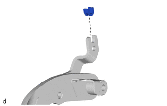
Remove the clutch pedal turnover bush from the clutch pedal sub-assembly.
31324A
10.REMOVE CLUTCH PEDAL SHAFT COLLAR
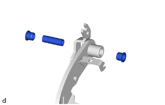
Remove the 2 clutch pedal bushes and clutch pedal shaft collar from the clutch pedal sub-assembly.
31453B
11.REMOVE CLUTCH MASTER CYLINDER PUSH ROD CLEVIS BUSH
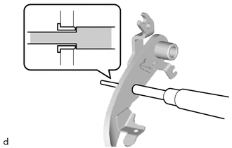
Using SST and a hammer, tap out the clutch master cylinder push rod clevis bush from the clutch pedal sub-assembly.
- SST
- 09201-01055 09950-70010 (09951-07100)
31321
12.REMOVE CLUTCH PEDAL PAD
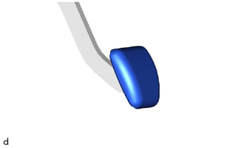
Remove the clutch pedal pad from the clutch pedal sub-assembly.