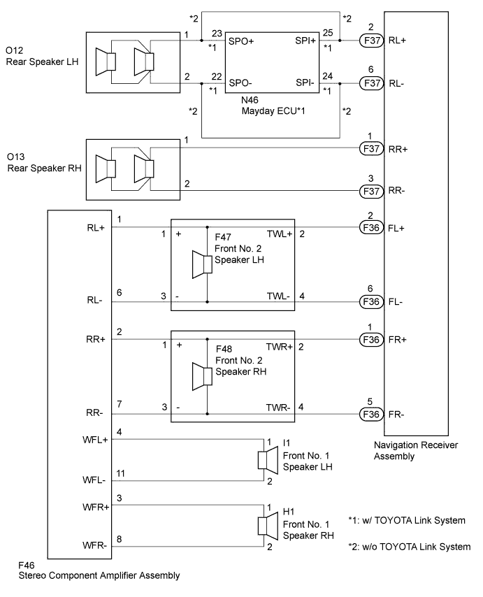
The sound signals amplified by the stereo component amplifier are sent to the speakers from the stereo component amplifier through this circuit. If there is a short in this circuit, the stereo component amplifier detects it and stops output to the speakers. Thus sound cannot be heard from the speakers even if there is no malfunction in the stereo component amplifier or speakers. If a short is detected in the speaker circuit, no sound can be heard from the speakers.
WIRING DIAGRAM
INSPECTION PROCEDURE
1. CHECK HARNESS AND CONNECTOR
Disconnect the F36 navigation receiver assembly connector.
Disconnect the F37 navigation receiver assembly connector.
Disconnect the H1 and I1 front No. 1 speaker connectors.
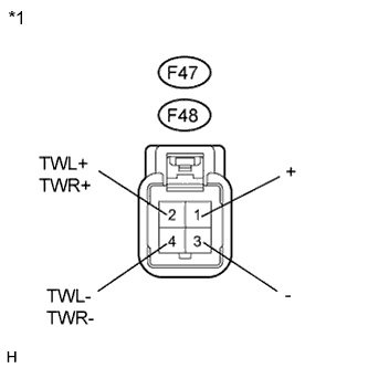
Disconnect the F47 and F48 front No. 2 speaker connectors.
Disconnect the O12 and O13 rear speaker connectors.
Disconnect the F46 stereo component amplifier assembly connector.
Disconnect the N46 mayday ECU connector.
Measure the resistance between each of the front No. 2 speakers and the navigation receiver assembly to check for an open circuit in the wire harness.
Standard Resistance:
Tester Connection
Condition
Specified Condition
F36-2 (FL+) - F47-2 (TWL+)
Always
Below 1 Ω
F36-6 (FL-) - F47-4 (TWL-)
Always
Below 1 Ω
F36-1 (FR+) - F48-2 (TWR+)
Always
Below 1 Ω
F36-5 (FR-) - F48-4 (TWR-)
Always
Below 1 Ω
Measure the resistance between each of the front No. 2 speakers and the stereo component amplifier assembly to check for an open circuit in the wire harness.
Standard Resistance:
Tester Connection
Condition
Specified Condition
F47-1 (+) - F46-1 (RL+)
Always
Below 1 Ω
F47-3 (-) - F46-6 (RL-)
Always
Below 1 Ω
F48-1 (+) - F46-2 (RR+)
Always
Below 1 Ω
F48-3 (-) - F46-7 (RR-)
Always
Below 1 Ω
w/o TOYOTA Link SystemMeasure the resistance between each of the rear speakers and the navigation receiver assembly to check for an open circuit in the wire harness.
Standard Resistance:
Tester Connection
Condition
Specified Condition
F37-2 (RL+) - O12-1
Always
Below 1 Ω
F37-6 (RL-) - O12-2
Always
Below 1 Ω
F37-1 (RR+) - O13-1
Always
Below 1 Ω
F37-3 (RR-) - O13-2
Always
Below 1 Ω
w/ TOYOTA Link SystemMeasure the resistance between each of the rear speakers, the mayday ECU and the navigation receiver assembly to check for an open circuit in the wire harness.
Standard Resistance:
Tester Connection
Condition
Specified Condition
F37-2 (RL+) - N46-25 (SPI+)
Always
Below 1 Ω
F37-6 (RL-) - N46-24 (SPI-)
Always
Below 1 Ω
F37-1 (RR+) - O13-1
Always
Below 1 Ω
F37-3 (RR-) - O13-2
Always
Below 1 Ω
N46-23 (SPO+) - O12-1
Always
Below 1 Ω
N46-22 (SPO-) - O12-2
Always
Below 1 Ω
Measure the resistance between each of the front No. 1 speakers and the stereo component amplifier assembly to check for an open circuit in the wire harness.
Standard Resistance:
Tester Connection
Condition
Specified Condition
I1-1 - F46-4 (WFL+)
Always
Below 1 Ω
I1-2 - F46-11 (WFL-)
Always
Below 1 Ω
H1-1 - F46-3 (WFR+)
Always
Below 1 Ω
H1-2 - F46-8 (WFR-)
Always
Below 1 Ω
Measure the resistance between each speaker and body ground to check for a short circuit in the wire harness.
Standard Resistance:
Tester Connection
Condition
Specified Condition
F47-1 (+) - Body ground
Always
10 kΩ or higher
F47-3 (-) - Body ground
Always
10 kΩ or higher
F47-2 (TWL+) - Body ground
Always
10 kΩ or higher
F47-4 (TWL-) - Body ground
Always
10 kΩ or higher
F48-1 (+) - Body ground
Always
10 kΩ or higher
F48-3 (-) - Body ground
Always
10 kΩ or higher
F48-2 (TWR+) - Body ground
Always
10 kΩ or higher
F48-4 (TWR-) - Body ground
Always
10 kΩ or higher
O12-1 - Body ground
Always
10 kΩ or higher
O12-2 - Body ground
Always
10 kΩ or higher
O13-1 - Body ground
Always
10 kΩ or higher
O13-2 - Body ground
Always
10 kΩ or higher
I1-1 - Body ground
Always
10 kΩ or higher
I1-2 - Body ground
Always
10 kΩ or higher
H1-1 - Body ground
Always
10 kΩ or higher
H1-2 - Body ground
Always
10 kΩ or higher
w/ TOYOTA Link SystemMeasure the resistance between the mayday ECU and body ground to check for a short circuit in the wire harness.
Standard Resistance:
Tester Connection
Condition
Specified Condition
N46-22 (SPO-) - Body ground
Always
10 kΩ or higher
N46-23 (SPO+) - Body ground
Always
10 kΩ or higher
N46-24 (SPI-) - Body ground
Always
10 kΩ or higher
N46-25 (SPI+) - Body ground
Always
10 kΩ or higher
NG
REPAIR OR REPLACE HARNESS OR CONNECTOR
OK
2. INSPECT FRONT NO. 1 SPEAKER
Resistance check
Measure the resistance between the terminals of the speaker.
Standard Resistance:
Tester Connection
Condition
Specified Condition
I1-1 - I1-2
Always
1.6 to 2.4 Ω
H1-1 - H1-2
Always
1.6 to 2.4 Ω
NOTICE:
The speaker should not be removed to check resistance.
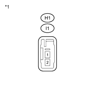
Text in Illustration
*1
Component without harness connected (Front No. 1 Speaker)