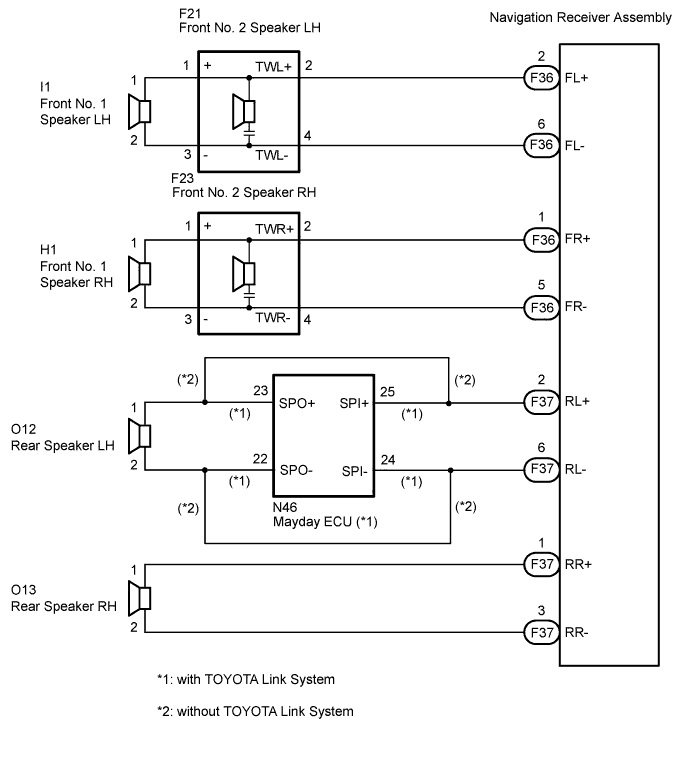
When the vehicle has a built-in type amplifier, a sound signal is sent from the navigation receiver assembly to the speakers via this circuit.
WIRING DIAGRAM
INSPECTION PROCEDURE
1. CHECK HARNESS AND CONNECTOR
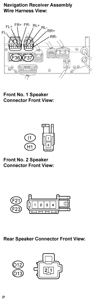
Disconnect the connectors shown in the illustration from the navigation receiver assembly and speakers.
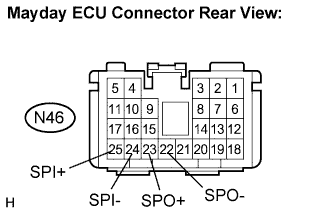
with TOYOTA Link SystemDisconnect the connector shown in the illustration from the mayday ECU.
Measure the resistance between each of the front No. 2 speakers and the navigation receiver assembly to check for an open circuit in the wire harness.
Standard resistance:
Below 1 Ω
Measure the resistance between each of the front No. 2 speakers and each of the front No. 1 speakers to check for an open circuit in the wire harness.
Standard resistance:
Below 1 Ω
without TOYOTA Link SystemMeasure the resistance between each of the rear speakers and the navigation receiver assembly to check for an open circuit in the wire harness.
Standard resistance:
Below 1 Ω
with TOYOTA Link SystemMeasure the resistance between the mayday ECU and the navigation receiver assembly to check for an open circuit in the wire harness.
Standard resistance:
Below 1 Ω
with TOYOTA Link SystemMeasure the resistance between the mayday ECU and the rear speaker LH to check for an open circuit in the wire harness.
Standard resistance:
Below 1 Ω
with TOYOTA Link SystemMeasure the resistance between the navigation receiver assembly and the rear speaker RH to check for an open circuit in the wire harness.
Standard resistance:
Below 1 Ω
without TOYOTA Link SystemMeasure the resistance between each speaker and body ground to check for a short circuit in the wire harness.
Standard resistance:
10 kΩ or higher
with TOYOTA Link SystemMeasure the resistance between each speaker, mayday ECU and body ground to check for a short circuit in the wire harness.
Standard resistance:
10 kΩ or higher
NG
REPAIR OR REPLACE HARNESS OR CONNECTOR
OK
2. INSPECT FRONT NO. 1 SPEAKER
Resistance check.
Measure the resistance between the terminals of the speaker.
Standard resistance:
Approximately 4 Ω
NG
REPLACE FRONT NO. 1 SPEAKER
OK
3. INSPECT FRONT NO. 2 SPEAKER
Check that the malfunction disappears when another speaker in good condition is installed.
Standard:
Malfunction disappears.
HINT:
Connect all the connectors to the front No. 2 speaker.
When there is a possibility that either the right or left front speaker is defective, inspect by interchanging the right one with the left one.
Perform the above inspection on both LH and RH sides.
OK
REPLACE FRONT NO. 2 SPEAKER
NG
4. INSPECT REAR SPEAKER
Resistance check.
Measure the resistance between the terminals of the speaker.
Standard resistance:
Approximately 4 Ω
NG
REPLACE REAR SPEAKER
OK
PROCEED TO NEXT CIRCUIT INSPECTION SHOWN IN PROBLEM SYMPTOMS TABLE