B2276 ACCR Signal Circuit Malfunction
Diagnostic trouble codes · Vehicles built from Jun 2009
DESCRIPTION
The main body ECU (instrument panel junction block assembly) will set this DTC if the ACCR signal sent from the ECM is ON for 40 seconds or more.| DTC No. |
DTC Detection Condition |
Trouble Area |
| B2276 |
ACCR output circuit inside main body ECU (instrument panel junction block assembly) or other related circuit is malfunctioning |
|
WIRING DIAGRAM
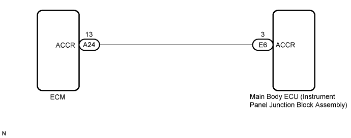

INSPECTION PROCEDURE
- HINT:
- When the main body ECU (instrument panel junction block assembly) is replaced with a new one and the negative (-) battery terminal is connected, the power source mode becomes the IG-ON mode. When the battery is removed and reinstalled, the power source mode that was selected when the battery was removed is restored.
- After the main body ECU (instrument panel junction block assembly) is replaced, perform the registration procedures for the engine immobiliser system.
| 1. CHECK DTC OUTPUT |

Clear the DTCs (Click here).
- HINT:
- After all DTCs are cleared, check if the trouble occurs again 50 seconds after the engine switch is turned on (IG).
Check for DTCs again.
- OK:
- DTC B2276 is not output.
|
|
||||

| OK | ||
 |
||
| ||
| 2. CHECK HARNESS AND CONNECTOR (MAIN BODY ECU (INSTRUMENT PANEL JUNCTION BLOCK) - ECM) |
Disconnect the E6 connector.
Disconnect the A24 ECM connector.
Measure the resistance according to the value(s) in the table below.
- Standard Resistance:
Tester Connection
Condition
Specified Condition
E6-3 (ACCR) - A24-13 (ACCR)
Always
Below 1 Ω
E6-3 (ACCR) - Body ground
Always
10 kΩ or higher
|
|
||||

| OK | |
 |
| 3. INSPECT MAIN BODY ECU (INSTRUMENT PANEL JUNCTION BLOCK ASSEMBLY) |
Reconnect the connectors.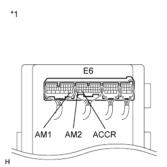
Measure the voltage according to the value(s) in the table below.
- Standard Voltage:
Tester Connection
Condition
Specified Condition
E6-3 (ACCR) - Body ground
Brake pedal depressed, shift P position, engine switch is pushed once → on (IG)
0.1 to 0.8 V (*1) → output voltage at terminal AM1 or AM2 is -2 V or more.
Text in Illustration *1
Component with harness connected
(Main Body ECU (Instrument Panel Junction Block Assembly))
- HINT:
- *1: Voltage is output only when the engine is cranking.
|
|
||||
| OK | |
|
| 4. CHECK MAIN BODY ECU (INSTRUMENT PANEL JUNCTION BLOCK ASSEMBLY) OPERATION |
After replacing the main body ECU (instrument panel junction block assembly) with a normally functioning ECU, check that the engine starts. Make sure the brake pedal is depressed and the shift position is P at this time.
Check that the engine switch mode can be changed by pushing the engine switch.
- HINT:
- Without depressing the brake pedal, push the engine switch repeatedly. Engine switch mode should turn from off to on (ACC) to on (IG) and back to off. With the brake pedal depressed, push the engine switch repeatedly. Engine switch mode should turn to ENGINE START from any status.
- OK:
- Engine can start normally.
- HINT:
- If engine does not start (Click here).
|
|
||||
| OK | ||
|
||
| ||