Home › BRAKE › PARKING BRAKE › PARKING BRAKE CABLEINSTALLATION
Removal / installation · Vehicles built Jun 2006 – Sep 2006
Versions by build date: Jun 2006 – Sep 2006 Oct 2006 – May 2009 from Jun 2009
1.
INSTALL NO. 3 PARKING BRAKE CABLE ASSEMBLY
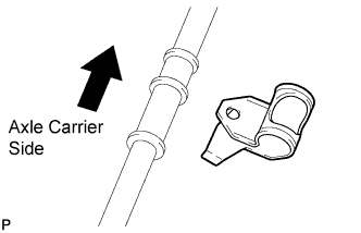
Install the parking brake cable clamp to the No. 3 parking brake cable assembly.
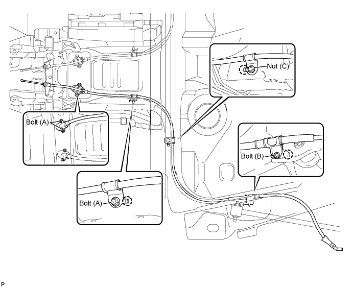
Install the No. 3 parking brake cable assembly with 3 bolts (A), bolt (B) and nut (C), and engage each claw.
Torque:
Bolt (A):
8.5 N*m{
87 kgf*cm
, 75 in.*lbf
}
Bolt (B) and Nut (C):
6.0 N*m{
61 kgf*cm
, 53 in.*lbf
}
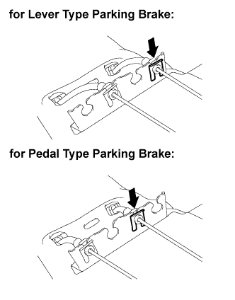
Using a brass bar and a hammer, install the clip to the No. 3 parking brake cable assembly.
2.
CONNECT NO. 3 PARKING BRAKE CABLE ASSEMBLY (for LHD)
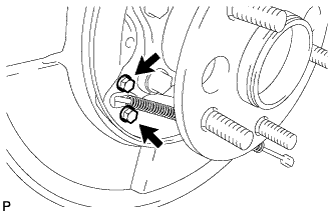
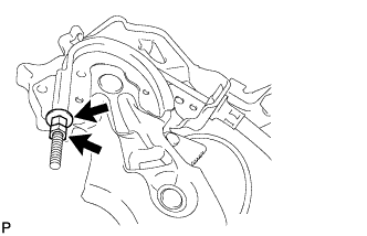
Connect the No. 3 parking brake cable assembly to the backing plate with the 2 bolts.
Torque:
8.0 N*m{
82 kgf*cm
, 71 in.*lbf
}
3.
CONNECT NO. 3 PARKING BRAKE CABLE ASSEMBLY (for RHD)
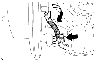
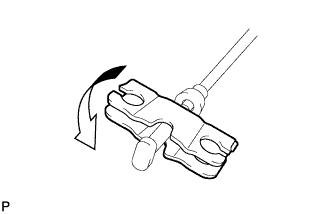
Turn and connect the No. 3 parking brake cable assembly. Using a brass bar and a hammer, install the clip to the No. 3 parking brake cable assembly.
4.
INSTALL NO. 2 PARKING BRAKE SHOE ASSEMBLY (for LHD)
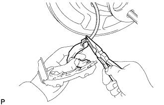
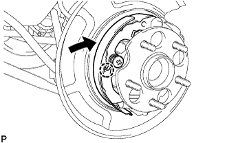
Using needle-nose pliers, connect the No. 3 parking brake cable assembly to the parking brake shoe lever.
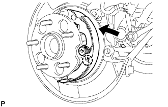
Install the No. 2 parking brake shoe assembly with the parking brake shoe hold down spring No. 2 pin, the parking brake shoe hold down spring No. 2 cup, the parking brake shoe hold down spring, and the parking brake shoe hold down spring No. 1 cup. Engage the claw of the parking brake shoe hold down spring No. 1 cup to the No. 2 parking brake shoe assembly.
5.
INSTALL PARKING BRAKE SHOE ADJUSTING SCREW SET (for LHD)
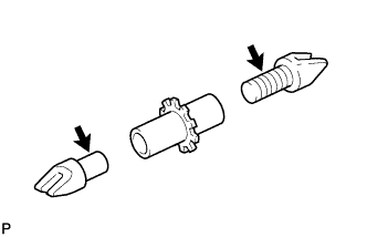
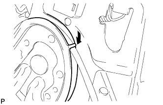
Apply high temperature grease to the parking brake adjusting screw as shown in the illustration.
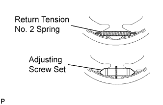
Install the parking brake shoe return tension No. 2 spring to the No. 1 parking brake shoe assembly and the No. 2 parking brake shoe assembly. Install the parking brake shoe adjusting screw set to the No. 1 parking brake shoe assembly and the No. 2 parking brake shoe assembly.
6.
INSTALL NO. 1 PARKING BRAKE SHOE ASSEMBLY (for LHD)
Install the No. 1 parking brake shoe assembly with the parking brake shoe hold down spring No. 1 pin, parking brake shoe hold down spring No. 2 cup, parking brake shoe hold down spring, and parking brake shoe hold down spring No. 1 cup. Engage the claw of the parking brake shoe hold down spring No. 1 cup to the No. 1 parking brake shoe assembly.
7.
INSTALL PARKING BRAKE SHOE STRUT (for LHD)
Install the parking brake shoe strut and the parking brake shoe strut compression spring to the No. 1 parking brake shoe assembly and No. 2 parking brake shoe assembly.
8.
INSTALL PARKING BRAKE SHOE RETURN TENSION NO. 1 SPRING (for LHD)
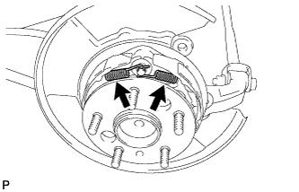
Using needle-nose pliers, install the 2 parking brake shoe return tension No. 1 springs.
HINT:
First install the front side spring and then the rear side spring.
9.
CHECK PARKING BRAKE INSTALLATION (for LHD)
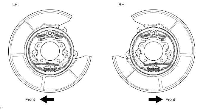
Check that each part is installed properly.
NOTICE:
There should be no oil or grease on the friction surface of the shoe lining and disc.
10.
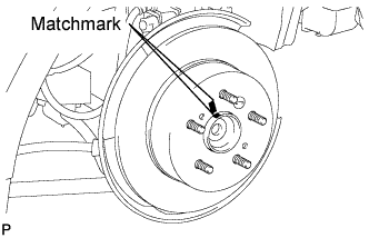
INSTALL REAR DISC (for LHD)
Align the matchmarks and install the rear disc.
11.
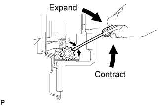
ADJUST PARKING BRAKE SHOE CLEARANCE (for LHD)
Temporarily install the hub nuts.
Remove the shoe adjusting hole plug.
Turn the shoe adjuster and expand the shoe until the disc locks. Turn and contract the shoe adjuster until the disc can rotate smoothly.
Standard:
Return 8 notches
Check that there is no brake drag against the shoe.
Install the shoe adjusting hole plug.
Remove the hub nuts.
12.
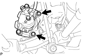
INSTALL REAR DISC BRAKE CALIPER ASSEMBLY (for LHD)
Install the rear disc brake caliper assembly with the 2 bolts.
Torque:
62 N*m{
632 kgf*cm
, 46 ft.*lbf
}
13.
INSTALL REAR WHEEL (for LHD)
Torque:
103 N*m{
1,050 kgf*cm
, 76 ft.*lbf
}
14.
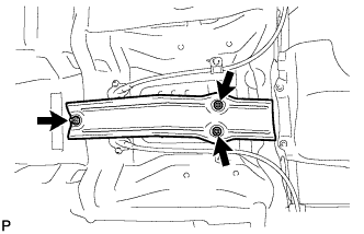
INSTALL NO. 2 FRONT FLOOR HEAT LOWER INSULATOR
Install the No. 2 front floor heat lower insulator with the 3 nuts.
Torque:
4.9 N*m{
50 kgf*cm
, 43 in.*lbf
}
15.
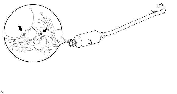
INSTALL CENTER EXHAUST PIPE ASSEMBLY
Install a new gasket onto the front exhaust pipe.
Install the center exhaust pipe assembly with the 2 bolts and 2 nuts.
Torque:
56 N*m{
571 kgf*cm
, 41 ft.*lbf
}
16.
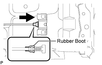
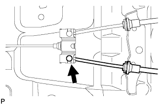
INSTALL NO. 4 PARKING BRAKE CABLE ASSEMBLY (for Pedal Type Parking Brake)
Install the No. 4 parking brake cable assembly to the parking brake equalizer.
Slide the rubber boot back as shown in the illustration.
17.
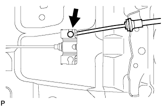
CONNECT NO. 2 PARKING BRAKE CABLE ASSEMBLY (for Pedal Type Parking Brake)
Connect the No. 2 parking brake cable assembly to the parking brake equalizer.
18.
CONNECT NO. 3 PARKING BRAKE CABLE ASSEMBLY (for Pedal Type Parking Brake)
Connect the No. 3 parking brake cable assembly to the parking brake equalizer.
19.
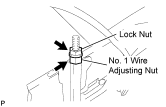
INSTALL NO. 1 PARKING BRAKE CABLE ASSEMBLY (for Lever Type Parking Brake)
Pass the No. 1 parking brake cable assembly through the parking brake lever sub-assembly.
Temporarily tighten the lock nut and the No. 1 wire adjusting nut.
NOTICE:
Fully tighten the lock nut when adjusting the parking brake lever travel.
Torque:
5.0 N*m{
51 kgf*cm
, 44 in.*lbf
}
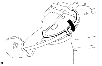
Bend the parking brake lever claw.
20.
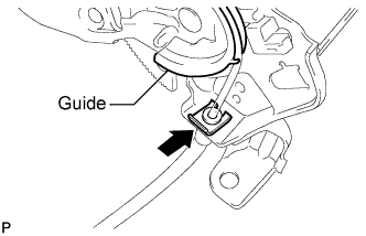
INSTALL NO. 1 PARKING BRAKE CABLE ASSEMBLY (for Pedal Type Parking Brake)
Pass the No. 1 parking brake cable assembly through the pedal guide. Using a brass bar and a hammer, install the clip to the No. 1 parking brake cable assembly.
Temporarily tighten the lock nut and the No. 1 wire adjusting nut.
NOTICE:
Fully tighten the lock nut and the No. 1 wire adjusting nut when adjusting the parking brake pedal travel.
Torque:
5.4 N*m{
55 kgf*cm
, 48 in.*lbf
}
Bend the parking brake pedal claw.
21.
INSTALL PARKING BRAKE LEVER SUB-ASSEMBLY (for Lever Type Parking Brake)
HINT:
Refer to the procedures from "INSTALL PARKING BRAKE LEVER SUB-ASSEMBLY". (Click here )
22.
INSTALL PARKING BRAKE PEDAL ASSEMBLY (for Pedal Type Parking Brake)
HINT:
Refer to the procedures from "INSTALL PARKING BRAKE PEDAL ASSEMBLY". (Click here )
23.
INSPECT FOR EXHAUST GAS LEAK
If gas is leaking, tighten the areas necessary to stop the leak. Replace the damaged parts as necessary.