C0365/28 Malfunction in Deceleration Sensor
Diagnostic trouble codes · Vehicles built from Jun 2009
Also covers:
- C1234/34 Yaw Rate Sensor Malfunction
Versions by build date: Jun 2006 – Sep 2006 Oct 2006 – May 2009 from Jun 2009
DESCRIPTION
The deceleration sensor is combined with the yaw rate and acceleration sensor.The brake actuator receives signals from the yaw rate and acceleration sensor via the CAN communication system.
If there is trouble in the CAN communication system, DTCs U0073/94 and U0123/62 are output.
| DTC No. |
DTC Detection Condition |
Trouble Area |
| C0365/28 |
When any of the following is detected:
|
|
| C1234/34 |
Sensor malfunction signal is received from the yaw rate sensor. |
|
WIRING DIAGRAM
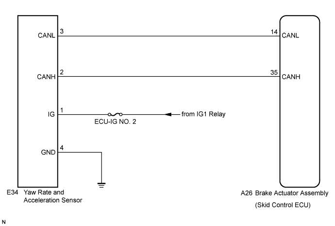

INSPECTION PROCEDURE
- HINT:
- Check the condition of each related circuit connector before troubleshooting (Click here).
- When U0073/94, U0100/65, U0123/62 and/or U0126/63 is output together with C0365/28, inspect and repair the trouble areas indicated by U0073/94, U0100/65, U0123/62 and/or U0126/63 first.
- Check the condition of each related circuit connector before troubleshooting (Click here).
| 1. CHECK DTC |

Clear the DTCs (Click here).
Start the engine.
At a speed of 30 km/h (18 mph) or more, drive the vehicle, turn the steering wheel, and decelerate (depress the brake pedal) the vehicle.
Turn the ignition switch on (IG) again and check that no CAN communication system DTC is output (Click here).
- Result:
Result
Proceed to
CAN communication system DTC is not output
A
CAN communication system DTC is output
B
|
|
||||

| A | |
 |
| 2. INSPECT YAW RATE AND ACCELERATION SENSOR INSTALLATION |
Check that the yaw rate and acceleration sensor has been installed properly (Click here).
- OK:
- The sensor should be tightened to the specified torque.
The sensor should not be tilted.
|
|
||||
| OK | |
|
| 3. INSPECT YAW RATE AND ACCELERATION SENSOR (IG TERMINAL) |
Disconnect the yaw rate and acceleration sensor connector.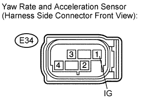
Turn the ignition switch on (IG).
Measure the voltage according to the value(s) in the table below.
- Standard voltage:
Tester Connection
Condition
Specified Condition
E34-1 (IG) - Body ground
Ignition switch on (IG)
10 to 14 V
|
|
||||
| OK | |
|
| 4. INSPECT YAW RATE AND ACCELERATION SENSOR (GND TERMINAL) |
Turn the ignition switch off.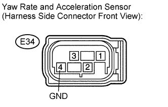
Measure the resistance according to the value(s) in the table below.
- Standard resistance:
Tester Connection
Condition
Specified Condition
E34-4 (GND) - Body ground
Ignition switch off
Below 1 Ω
|
|
||||
| OK | |
|
| 5. RECONFIRM DTC |
Clear the DTCs (Click here).
Start the engine.
At a speed of 30 km/h (18 mph) or more, drive the vehicle, turn the steering wheel, and decelerate (depress the brake pedal) the vehicle.
Turn the ignition switch on (IG) again and check that no CAN communication system DTC is output (Click here).
- HINT:
- Reinstall the sensors, connectors, etc. and restore the vehicle to its prior condition before rechecking for DTCs.
- Result:
Result
Proceed to
DTC is output
A
DTC is not output (When troubleshooting in accordance with the PROBLEM SYMPTOMS TABLE)
B
DTC is not output (When troubleshooting in accordance with the DTC CHART)
C
|
|
||||
|
|
||||
| A | ||
 |
||
| ||