Ignition Switch Circuit
Circuit diagnosis · Vehicles built from Jun 2006
DESCRIPTION
The main body ECU determines the ignition position (OFF, ACC, ON) based on signals from the IG or ACC circuit.WIRING DIAGRAM
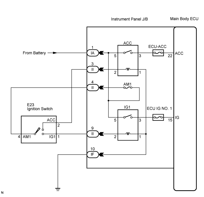

INSPECTION PROCEDURE
| 1. READ VALUE USING INTELLIGENT TESTER |

Connect the intelligent tester to the DLC3.
Turn the ignition switch to the ON position.
Turn the intelligent tester main switch on.
Select the item below in the Data List and read the display on the intelligent tester.
MAIN BODY (Main Body ECU): Item
Test Details
Diagnostic Note
IG SW
ignition switch ON signal ON/OFF
-
ACC SW
ignition switch ACC signal ON/OFF
-
- OK:
- When the ignition switch is operated, the display changes as shown in the table.
|
|
||||

| OK | ||
 |
||
| ||
| 2. CHECK HARNESS AND CONNECTOR (BATTERY - INSTRUMENT PANEL J/B) |
Disconnect the IA J/B connector.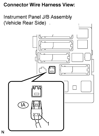
Measure the voltage according to the value(s) in the table below.
- Standard voltage:
Tester Connection
Condition
Specified Condition
IA-1 - Body ground
Ignition switch ON
10 to 14 V
|
|
||||

| OK | |
 |
| 3. INSPECT IGNITION OR STARTER SWITCH ASSEMBLY |
Disconnect the E23 switch connector from the ignition switch.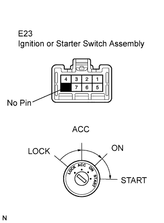
Measure the resistance according to the value(s) in the table below.
- Standard resistance:
Tester Connection
Condition
Specified Condition
1 - 4
Ignition switch ON
Below 1 Ω
2 - 4
Ignition switch ACC
Below 1 Ω
|
|
||||
| OK | |
|
| 4. CHECK HARNESS AND CONNECTOR (INSTRUMENT PANEL J/B - INSTRUMENT PANEL J/B) |
Reconnect the E23 switch connector.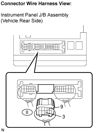
Disconnect the II J/B connector.
Measure the resistance according to the value(s) in the table below.
- Standard resistance:
Tester Connection
Condition
Specified Condition
II-4 - II-9
Ignition switch ON
Below 1 Ω
II-4 - II-3
Ignition switch ACC
Below 1 Ω
|
|
||||
| OK | |
|
| 5. CHECK HARNESS AND CONNECTOR (INSTRUMENT PANEL J/B - BODY GROUND) |
Disconnect the IF J/B connector.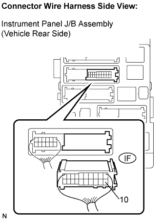
Measure the resistance according to the value(s) in the table below.
- Standard resistance:
Tester Connection
Specified Condition
IF-10 - Body ground
Below 1 Ω
|
|
||||
| OK | ||
|
||
| ||