Home › BODY ELECTRICAL › PARK ASSIST / MONITORING › TOYOTA PARKING ASSIST-SENSOR SYSTEM (for 6 Sensor Type)Front Clearance Sonar Sensor Circuit
Circuit diagnosis · Vehicles built from Jun 2009
Versions by build date: Oct 2006 – May 2009 from Jun 2009
DESCRIPTION
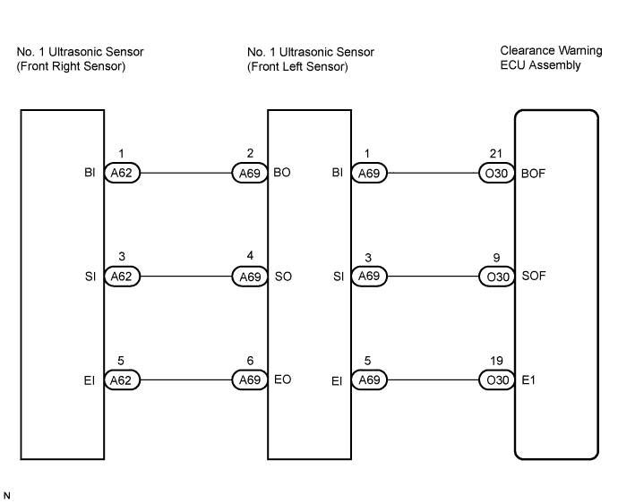
There is an open or short circuit in the communication line between the front sensors and the clearance warning ECU, or there is a malfunction in a front sensor. WIRING DIAGRAM
INSPECTION PROCEDURE
1. CHECK TOYOTA PARKING ASSIST-SENSOR SYSTEM
Check the operation of the Toyota parking assist-sensor system (Click here ).
Result:
Result
Proceed to
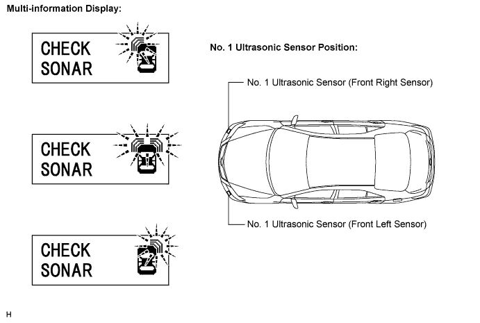
Warning message is displayed on multi-information display and all front clearance sensor indicators are blinking
A
Warning message is displayed on multi-information display and front left clearance sensor or front right clearance sensor indicator is blinking
B
B
A
2. CHECK HARNESS AND CONNECTOR (CLEARANCE WARNING ECU - FRONT LEFT SENSOR)
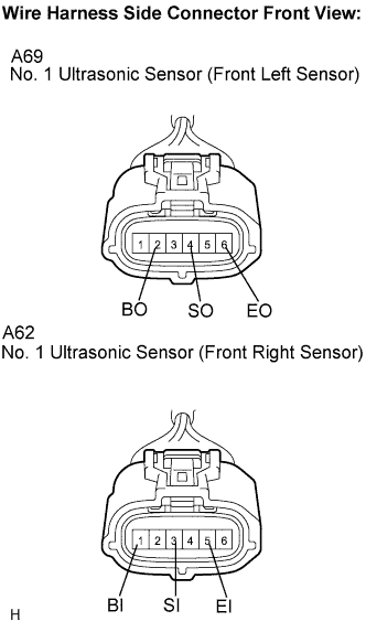
Disconnect the O30 ECU connector. Disconnect the A69 sensor connector.
Measure the resistance according to the value(s) in the table below.
Standard resistance:
Tester Connection
Condition
Specified Condition
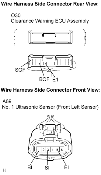
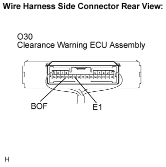
O30-21 (BOF) - A69-1 (BI)
Always
Below 1 Ω
O30-9 (SOF) - A69-3 (SI) O30-19 (E1) - A69-5 (EI)
O30-21 (BOF) - Body ground
10 kΩ or higher
O30-9 (SOF) - Body ground O30-19 (E1) - Body ground
NG
REPAIR OR REPLACE HARNESS OR CONNECTOR
OK
3. INSPECT CLEARANCE WARNING ECU ASSEMBLY
Reconnect the O30 ECU connector. Measure the resistance according to the value(s) in the table below.
Standard resistance:
Tester Connection
Condition
Specified Condition
O30-19 (E1) - Body ground
Always
Below 1 Ω
Measure the voltage according to the value(s) in the table below.
Standard voltage:
Tester Connection
Condition
Specified Condition
O30-21 (BOF) - Body ground
Ignition switch on (IG)
7 to 9 V
NG
REPLACE CLEARANCE WARNING ECU ASSEMBLY (Click here )
OK
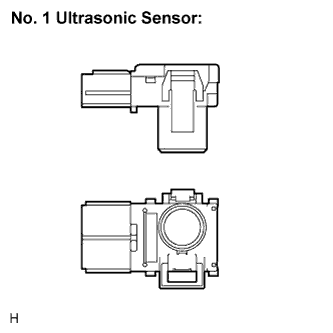
4. REPLACE NO. 1 ULTRASONIC SENSOR (FRONT LEFT SENSOR)
Replace the ultrasonic sensor (Click here ) with a normally functioning sensor.
HINT:
All the corner sensors are the same. Switch the right and left sensors to confirm if the sensors function normally.
NEXT
5. CHECK TOYOTA PARKING ASSIST-SENSOR SYSTEM
Check the operation of the Toyota parking assist-sensor system (Click here ).
Result:
Result
Proceed to
Toyota parking assist-sensor system malfunction
A
Toyota parking assist-sensor system normal operation
B
B
A
6. CHECK HARNESS AND CONNECTOR (FRONT LEFT SENSOR - FRONT RIGHT SENSOR)
Disconnect the A69 and A62 sensor connectors. Measure the resistance according to the value(s) in the table below.
Standard resistance:
Tester Connection
Condition
Specified Condition
A69-2 (BO) - A62-1 (BI)
Always
Below 1 Ω
A69-4 (SO) - A62-3 (SI) A69-6 (EO) - A62-5 (EI)
A69-2 (BO) - Body ground
10 kΩ or higher
A69-4 (SO) - Body ground A69-6 (EO) - Body ground
NG
REPAIR OR REPLACE HARNESS OR CONNECTOR
OK
7. REPLACE NO. 1 ULTRASONIC SENSOR (FRONT RIGHT SENSOR)
Replace the ultrasonic sensor (Click here ) with a normally functioning sensor.
HINT:
All the corner sensors are the same. Switch the right and left sensors to confirm if the sensors function normally.
NEXT
8. CHECK TOYOTA PARKING ASSIST-SENSOR SYSTEM
Check the operation of the Toyota parking assist-sensor system (Click here ).
Result:
Result
Proceed to
Toyota parking assist-sensor system malfunction
A
Toyota parking assist-sensor system normal operation
B
B
A
PROCEED TO NEXT CIRCUIT INSPECTION SHOWN IN PROBLEM SYMPTOMS TABLE (Click here )