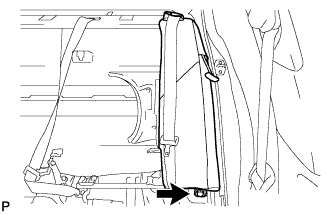
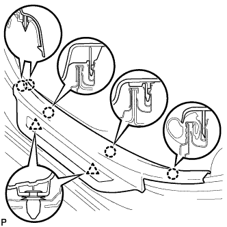
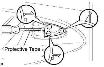
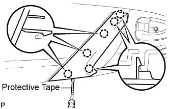
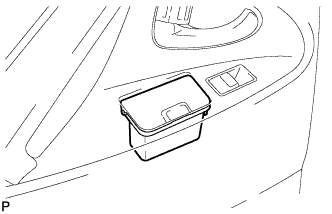
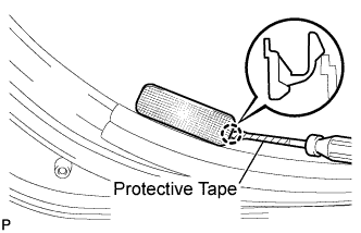
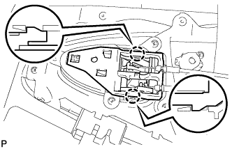
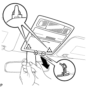
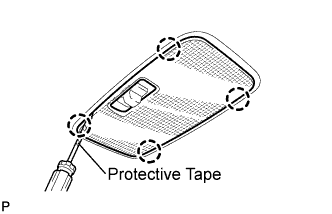
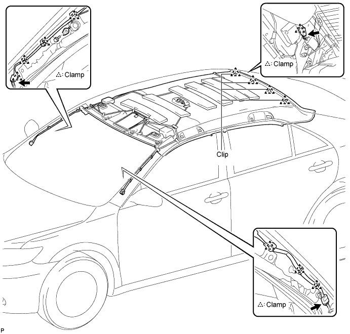
Using a screwdriver with the tip wrapped with protective tape, disengage the claw and remove the courtesy light assembly.
Disconnect the connector.
35.
REMOVE REAR DOOR TRIM BOARD SUB-ASSEMBLY LH
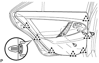
Remove the 3 screws.
Using a clip remover, disengage the 7 clips.
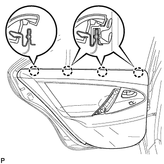
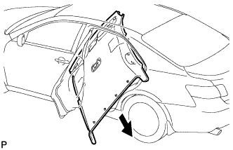
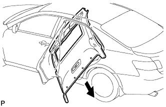
Raise the rear door trim board to disengage the 4 claws and remove the rear door trim board together with the rear door inner glass weatherstrip.
Disconnect the connector.
Disengage the 2 claws and disconnect the rear door inside handle sub-assembly.
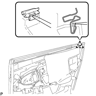
Disengage the clip as shown in the illustration and remove the No. 1 door scuff plate clamp from the rear door trim board.
36.
REMOVE REAR DOOR INNER GLASS WEATHERSTRIP LH
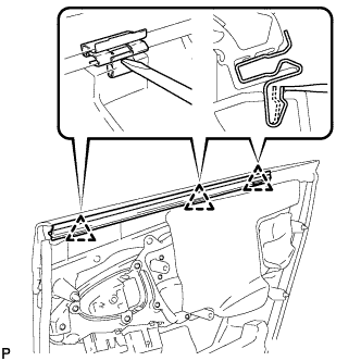
Disengage the 3 clips as shown in the illustration and remove the rear door inner glass weatherstrip from the rear door trim board.
37.
REMOVE FRONT DOOR SCUFF PLATE LH
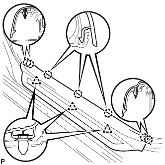
Disengage the 7 claws and 3 clips, and remove the front door scuff plate LH.
38.
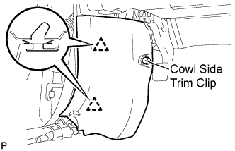
REMOVE COWL SIDE TRIM SUB-ASSEMBLY LH
Remove the cowl side trim clip.
Disengage the 2 clips and remove the cowl side trim sub-assembly LH.
39.
REMOVE FRONT DOOR OPENING TRIM WEATHERSTRIP LH
40.
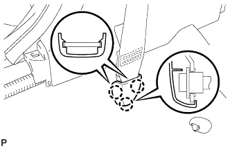
REMOVE LAP BELT OUTER ANCHOR COVER (for LH Side)
Disengage the 3 claws and remove the lap belt outer anchor cover.
41.
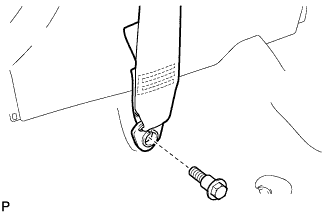
DISCONNECT FRONT SEAT OUTER BELT ASSEMBLY LH
Remove the bolt and disconnect the floor end of the front seat outer belt assembly LH.
42.
REMOVE LOWER CENTER PILLAR GARNISH LH
Disengage the 2 claws and 2 clips, and remove the lower center pillar garnish LH.
43.
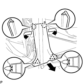
REMOVE UPPER CENTER PILLAR GARNISH LH
Remove the bolt.
Disengage the clip and remove the upper center pillar garnish LH.
44.
REMOVE FRONT DOOR SCUFF PLATE RH
HINT:
Use the same procedure for the RH and LH side (Click here).
45.
REMOVE COWL SIDE TRIM SUB-ASSEMBLY RH
HINT:
Use the same procedure for the RH and LH side (Click here).
46.
REMOVE FRONT DOOR OPENING TRIM WEATHERSTRIP RH
47.
REMOVE LAP BELT OUTER ANCHOR COVER (for RH Side)
HINT:
Use the same procedure for the RH and LH side (Click here).
48.
DISCONNECT FRONT SEAT OUTER BELT ASSEMBLY RH
HINT:
Use the same procedure for the RH and LH side (Click here).
49.
REMOVE LOWER CENTER PILLAR GARNISH RH
HINT:
Use the same procedure for the RH and LH side (Click here).
50.
REMOVE UPPER CENTER PILLAR GARNISH RH
HINT:
Use the same procedure for the RH and LH side (Click here).
51.
REMOVE ROOF SIDE INNER GARNISH LH
Disengage the 5 clips and 2 claws, and remove the roof side inner garnish LH.
52.
REMOVE ROOF SIDE INNER GARNISH RH
HINT:
Use the same procedure for the RH and LH side (Click here).
53.
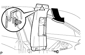
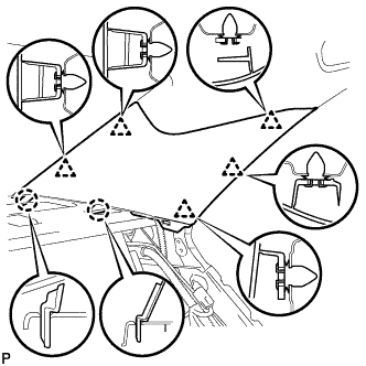
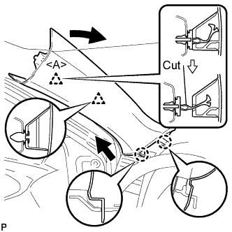
REMOVE FRONT PILLAR GARNISH LH
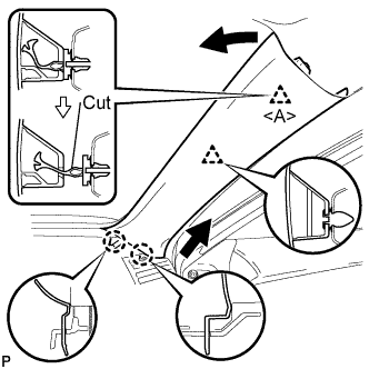
Pull the upper part of the garnish toward the inside of the cabin and disengage the 2 clips.
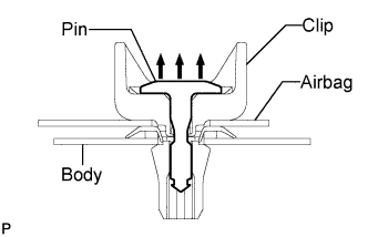
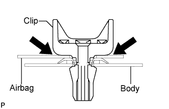
Cut off the clip <A>.
Disengage the 2 claws and remove the front pillar garnish LH.
Remove the clip <A> from the vehicle body.
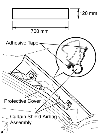
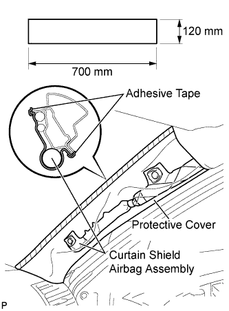
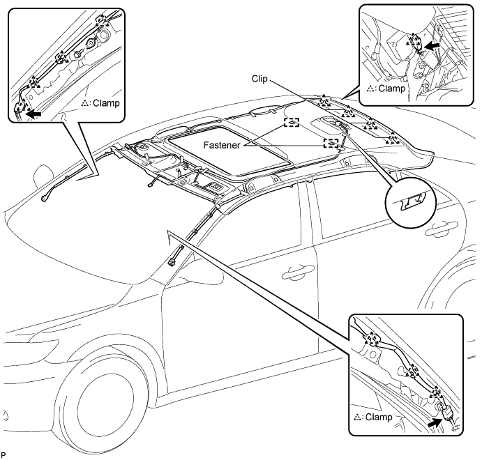
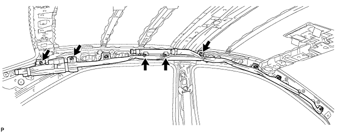
Protect the curtain shield airbag assembly.
Cover the airbag with a 700 mm (27.56 in.) x 120 mm (4.72 in.) cloth or piece of nylon and fix the ends of the cover with tape, as shown in the illustration.
NOTICE:
Cover the curtain shield airbag with a protective cover as soon as the front pillar garnish is removed.
54.
REMOVE FRONT PILLAR GARNISH RH
Pull the upper part of the garnish toward the inside of the cabin and disengage the 2 clips.
Cut off the clip <A>.
Disengage the 2 claws and remove the front pillar garnish RH.
Remove the clip <A> from the vehicle body.
Protect the curtain shield airbag assembly.
Cover the airbag with a 700 mm (27.56 in.) x 120 mm (4.72 in.) cloth or piece of nylon and fix the ends of the cover with tape, as shown in the illustration.
NOTICE:
Cover the curtain shield airbag with a protective cover as soon as the front pillar garnish is removed.
55.
REMOVE RAIN SENSOR COVER (w/ Rain Sensor)
Remove the rain sensor cover.
56.
REMOVE ROOF CONSOLE BOX ASSEMBLY
Using a moulding remover, disengage the 2 clips and 2 claws.
Disconnect the connectors and remove the roof console box assembly.
57.
REMOVE VISOR ASSEMBLY LH
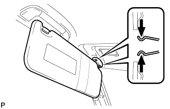
Using a moulding remover, disengage the 4 claws and remove the visor bracket cover.
Disengage the 2 clips and remove the visor assembly LH.
58.
REMOVE VISOR ASSEMBLY RH
HINT:
Use the same procedure for the RH and LH side (Click here).
59.
REMOVE VISOR HOLDER
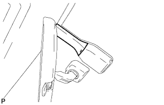
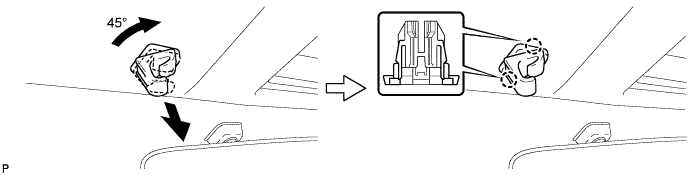
Turn the visor holder approximately 45° and pull it out as shown in the illustration.
Disengage the 2 claws and remove the visor holder.
HINT:
Use the same procedure for the RH side and the LH side.
60.
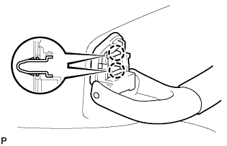
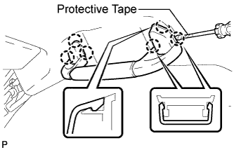
REMOVE FRONT ASSIST GRIP SUB-ASSEMBLY (for Driver Side)
with Assist Grip:
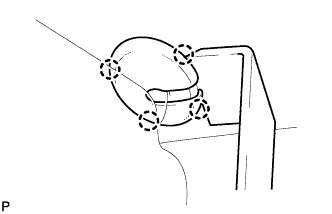
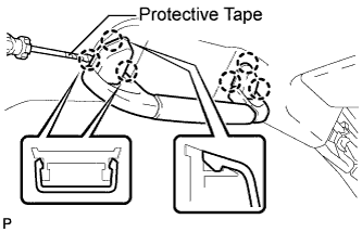
Using a screwdriver, disengage the 6 claws and remove the 2 assist grip covers.
HINT:
Tape the screwdriver tip before use.
Disengage the 2 clips and remove the front assist grip sub-assembly.
61.
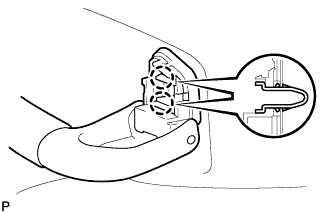
REMOVE FRONT ASSIST GRIP SUB-ASSEMBLY (for Front Passenger Side)
Using a screwdriver, disengage the 6 claws and remove the 2 assist grip covers.
HINT:
Tape the screwdriver tip before use.
Disengage the 2 clips and remove the front assist grip sub-assembly.
62.
REMOVE REAR ASSIST GRIP SUB-ASSEMBLY
HINT:
Use the same procedure for the rear side and the front side (Click here).
Using a screwdriver, disengage the 4 claws and remove the lens cover.
HINT:
Tape the screwdriver tip before use.
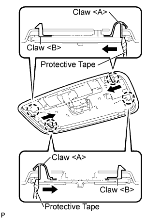
Using a screwdriver, disengage the 2 claws <A> as shown in the illustration.
HINT:
Tape the screwdriver tip before use.
Disengage the 2 claws <B> and remove the No. 1 room light assembly.
Disconnect the room light connector.
64.
REMOVE SPOT LIGHT ASSEMBLY (w/ Sliding Roof)
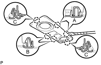
Using a screwdriver, disengage the 2 claws labeled A and 2 claws labeled B from the vehicle body.
HINT:
Tape the screwdriver tip before use.
Using a screwdriver, disengage the 2 claws labeled C and remove the spot light assembly from the headlining.
HINT:
Tape the screwdriver tip before use.
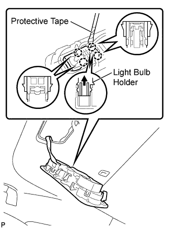
Using a screwdriver, disengage the 4 claws.
HINT:
Tape the screwdriver tip before use.
Pull the light bulb holder in the direction indicated by the arrow in the illustration to detach the claw. Then remove the spot light assembly from the light bulb holder.
65.
REMOVE SUN ROOF OPENING TRIM MOULDING (w/ Sliding Roof)