Sliding Roof ECU Power Source Circuit
Circuit diagnosis · Vehicles built Jun 2006 – Sep 2006
Versions by build date: Jun 2006 – Sep 2006 from Oct 2006
DESCRIPTION
The sliding roof drive gear sub-assembly (sliding roof control ECU) receives signals from the sliding roof switch and activates the sliding roof. However, malfunctions in the fuse, wire harness or sliding roof drive gear sub-assembly (sliding roof control ECU) may cause the sliding roof system to stop operating.WIRING DIAGRAM
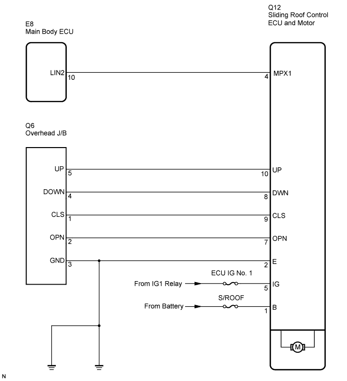

INSPECTION PROCEDURE
| 1. PERFORM ACTIVE TEST USING INTELLIGENT TESTER (SLIDING ROOF OPERATION) |

Select the ACTIVE TEST, use the intelligent tester to generate a control command, and then check that the sliding roof slides open/close and tilts up/down.
- SLIDE ROOF:
Tester Display
Test Part
Control Range
Diagnostic Note
Slide Roof
(Slide Roof)
Operate sliding roof SLIDE CLOSE/TILT UP
CLOS/UP: Sliding roof SLIDE CLOSE or TILT UP operation occurs.
OFF: Sliding roof is not operating
-
Slide Roof
(Slide Roof)
Operate sliding roof SLIDE OPEN/TILT DOWN
OPN/DWN: Sliding roof SLIDE OPEN or TILT DOWN operation occurs
OFF: Sliding roof is not operating
-
- OK:
- Sliding roof operates normally.
|
|
||||

| OK | ||
 |
||
| ||
| 2. INSPECT FUSE (S/ROOF, ECU-IG NO. 1) |
Remove the S/ROOF and ECU-IG No. 1 fuses from the instrument panel J/B.
Measure the resistance of the fuses.
- Standard resistance:
- Below 1 Ω
|
|
||||

| OK | |
 |
| 3. CHECK WIRE HARNESS (SLIDING ROOF CONTROL ECU - BATTERY AND BODY GROUND) |
Disconnect the Q12 connector.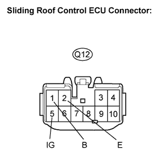
Measure the voltage and resistance according to the value(s) in the table below.
- Standard voltage:
Tester Connection
Condition
Specified Condition
B (Q12-1) - Body ground
Always
10 to 14 V
IG (Q12-5) - Body ground
Ignition switch ON
10 to 14 V
IG (Q12-5) - Body ground
Ignition switch off
Below 1 V
- Standard resistance:
Tester Connection
Specified Condition
E (Q12-2) - Body ground
Below 1 Ω
|
|
||||
| OK | ||
|
||
| ||