INSTALLATION
Removal / installation · Vehicles built Oct 2006 – May 2009
Versions by build date: Oct 2006 – May 2009 from Jun 2009
| 1.
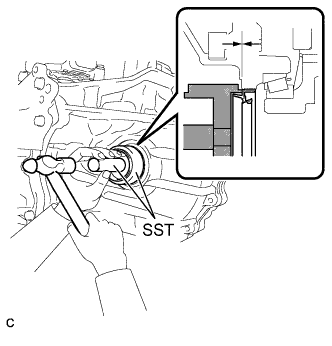
INSTALL DIFFERENTIAL SIDE BEARING RETAINER OIL SEAL |
 |
- Using SST and a hammer, install a new oil seal to the transaxle case.
- SST
- 09316-10010
09950-70010
(09951-07100)
- Oil seal installation depth:
- -0.5 to 0.5 mm (-0.020 to 0.020 in.)
Coat the lip of the oil seal with MP grease.
| 2.
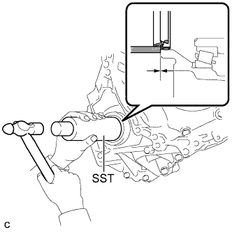
INSTALL TRANSAXLE HOUSING OIL SEAL |
|
- Using SST and a hammer, install a new oil seal to the transaxle housing.
- SST
- 09308-14010
- Oil seal installation depth:
- -0.5 to 0.5 mm (-0.020 to 0.020 in.)
Coat the lip of the oil seal with MP grease.
| 3.
INSTALL FRONT DRIVE SHAFT ASSEMBLY LH
|
|
- Coat the spline of the inboard joint shaft assembly with ATF.
Align the shaft splines and install the drive shaft assembly LH with a brass bar and hammer.
- NOTICE:
- Set the shaft snap ring with the opening side facing down.
- Be careful not to damage the drive shaft dust cover, boot, and oil seal.
- Move the drive shaft assembly while keeping it level.
| 4.
INSTALL FRONT DRIVE SHAFT ASSEMBLY RH
|
|
- Coat the spline of the inboard joint shaft assembly with ATF.
Install the front drive shaft assembly RH.
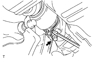
Using a screwdriver, install a new bearing bracket hole snap ring.
- NOTICE:
- Do not damage the boot and oil seal.
- Move the drive shaft assembly while keeping it level.
Install a new bolt.
-
Torque:
- 32 N*m{
330 kgf*cm
, 24 ft.*lbf
}
| 5.
INSTALL FRONT AXLE ASSEMBLY LH
|
|
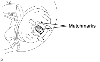
- Align the matchmarks and install the front drive shaft assembly to the front axle hub sub-assembly.
- NOTICE:
- Be careful not to damage the drive shaft boot and speed sensor rotor.
| 6.
INSTALL FRONT AXLE ASSEMBLY RH |
|
- HINT:
- Use the same procedures as described for the LH side.
| 7.
INSTALL FRONT SUSPENSION LOWER NO. 1 ARM LH
|
|
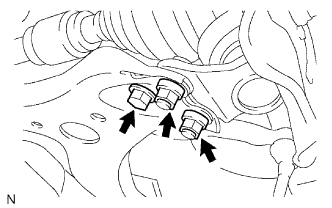
- Install the lower ball joint to the front suspension lower No. 1 arm with the bolt and 2 nuts.
-
Torque:
- 75 N*m{
765 kgf*cm
, 55 ft.*lbf
}
| 8.
INSTALL FRONT SUSPENSION LOWER NO. 1 ARM RH |
|
- HINT:
- Use the same procedures as described for the LH side.
| 9.
INSTALL TIE ROD END SUB-ASSEMBLY LH
|
|
Install the tie rod end sub-assembly to the steering knuckle with the nut.
-
Torque:
- 49 N*m{
500 kgf*cm
, 36 ft.*lbf
}
Install a new cotter pin.
- NOTICE:
- If the holes for the cotter pin are not aligned, tighten the nut up to 60° further.
| 10.
INSTALL TIE ROD END SUB-ASSEMBLY RH |
|
- HINT:
- Use the same procedures as described for the LH side.
| 11.
INSTALL FRONT SPEED SENSOR LH
|
|
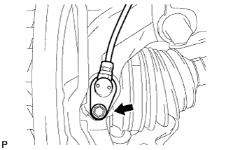
- Install the front speed sensor to the steering knuckle with the bolt.
-
Torque:
- 8.0 N*m{
82 kgf*cm
, 71 in.*lbf
}
- NOTICE:
- Prevent foreign matter from adhering to the speed sensor.
- Be careful not to damage the speed sensor.
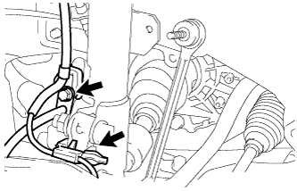
- Install the flexible hose and the speed sensor to the shock absorber with the bolt and set the sensor clip on the knuckle.
-
Torque:
- 19 N*m{
192 kgf*cm
, 14 ft.*lbf
}
- NOTICE:
- Be careful not to damage the speed sensor.
- Prevent foreign matter from adhering to the speed sensor.
- Do not twist the sensor wire when installing the speed sensor.
| 12.
INSTALL FRONT SPEED SENSOR RH |
|
- HINT:
- Use the same procedures as described for the LH side.
| 13.
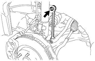
INSTALL FRONT STABILIZER LINK ASSEMBLY LH
|
|
- Install the stabilizer link assembly with the nut.
-
Torque:
- 74 N*m{
755 kgf*cm
, 55 ft.*lbf
}
- HINT:
- If the ball joint turns together with the nut, use a hexagon wrench (6 mm) to hold the stud.
| 14.
INSTALL FRONT STABILIZER LINK ASSEMBLY RH |
|
- HINT:
- Use the same procedures as described for the LH side.
| 15.
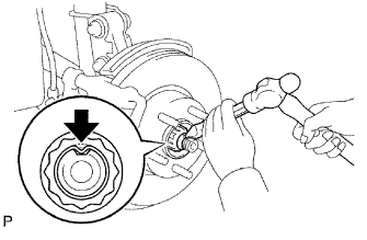
INSTALL FRONT AXLE HUB NUT LH
|
|
- Using a socket wrench (30 mm), install a new axle hub nut.
-
Torque:
- 294 N*m{
3,000 kgf*cm
, 217 ft.*lbf
}
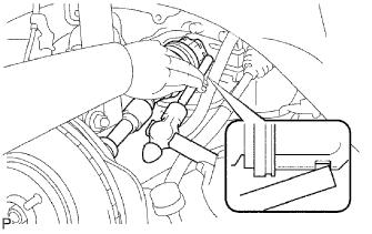
Using a chisel and hammer, stake the front axle hub nut.
| 16.
INSTALL FRONT AXLE HUB NUT RH |
|
- HINT:
- Use the same procedures as described for the LH side.
| 17.
INSTALL FRONT WHEELS
|
|
-
Torque:
- 103 N*m{
1,050 kgf*cm
, 76 ft.*lbf
}
| 18.
ADD AUTOMATIC TRANSAXLE FLUID |
|
- HINT:
-
Click here.
| 19.
ADJUST FRONT WHEEL ALIGNMENT |
|
- HINT:
-
Click here.
| 20.
CHECK ABS SPEED SENSOR SIGNAL |
|
ABS: Click here.
VSC: Click here.