2006-2011 Camry Aurion · Service Manual ENGINE

REMOVAL

Removal / installation · Vehicles built Jun 2006 – Sep 2006

Versions by build date: Jun 2006 – Sep 2006 Oct 2006 – May 2009 from Jun 2009


1. DISCHARGE FUEL SYSTEM PRESSURE

HINT:
Click here.


2. DISCONNECT CABLE FROM NEGATIVE BATTERY TERMINAL

3. REMOVE FRONT WHEEL RH

4. REMOVE ENGINE UNDER COVER LH

5. REMOVE ENGINE UNDER COVER RH

6. REMOVE FRONT FENDER APRON SEAL RH

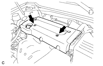
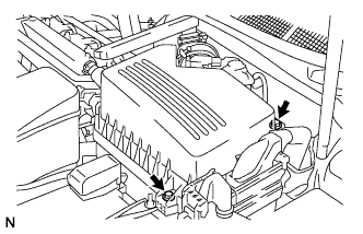
7. REMOVE NO. 1 ENGINE COVER SUB-ASSEMBLY

  1. A134904
    Remove the 2 nuts and cover.


8. DRAIN ENGINE OIL
  1. Remove the oil filler cap.

  1. Remove the oil drain plug and drain the oil into a container.


9. DRAIN ENGINE COOLANT

NOTICE:
Do not remove the radiator cap sub-assembly while the engine and radiator are still hot. Pressurized, hot engine coolant and steam may be released and cause serious burns.

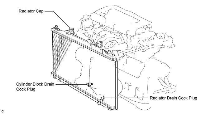
  1. Remove the radiator cap sub-assembly from the radiator assembly.

  1. Loosen the radiator drain cock plug and cylinder block drain cock plug, then drain the coolant.

    A136224E04

    HINT:
    Collect the coolant in a container and dispose of it according to the regulations in your area.


10. REMOVE WINDSHIELD WIPER MOTOR AND LINK ASSEMBLY

HINT:
Click here.


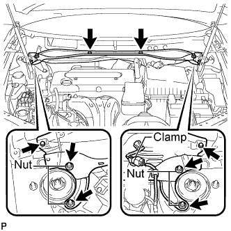
11. REMOVE COWL TOP OUTER FRONT PANEL SUB-ASSEMBLY

  1. C141972E01
    Disengage the clamp.

  1. Remove the 4 nuts, the 4 bolts and the cowl top outer front panel sub-assembly.


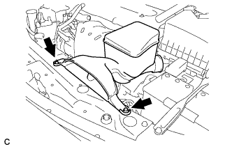
12. REMOVE AIR CLEANER INLET ASSEMBLY

  1. A134903
    Remove the 2 bolts, clamp and air cleaner inlet.


13. REMOVE AIR CLEANER CAP SUB-ASSEMBLY

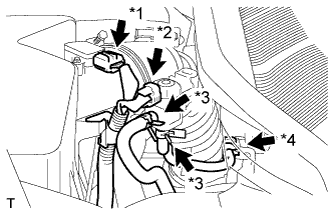
  1. A144946E01
    Disconnect the mass air flow meter connector (*1).

  1. Disconnect the purge VSV connector (*2).

  1. Disconnect the 2 purge VSV vacuum hoses (*3).

  1. Disconnect the purge line hose from the clamp (*4).

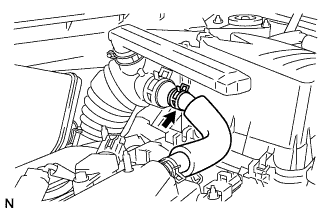
  1. A146036
    Disconnect the No. 2 ventilation hose from the air cleaner hose.

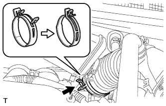
  1. A135668
    Lock the No. 1 air cleaner hose clamp, and then disconnect the No. 1 air cleaner hose from the throttle body.

  1. A146037
    Remove the 2 bolts and air cleaner cap.

  1. Remove the air cleaner filter element from the air cleaner case.


14. REMOVE AIR CLEANER CASE SUB-ASSEMBLY

  1. A134905
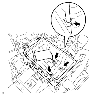
    Disconnect the hose clamp.

  1. Remove the 3 bolts and air cleaner case.


15. REMOVE BATTERY

  1. A134906
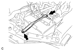
    Loosen the bolt and nut, and remove the battery clamp.

  1. Remove the battery and battery tray.


16. REMOVE THROTTLE BODY

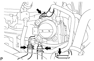
  1. A128919E01
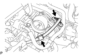
    Disconnect the throttle position sensor connector and wire harness clamp.

  1. A128920E01
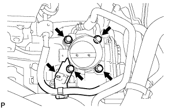
    Remove the 4 bolts, and then remove the fuel pipe support and throttle body.

  1. A128921E01
    Disconnect the purge line hose from the throttle body.

  1. Disconnect the water by-pass hose from the throttle body.

  1. Disconnect the No. 2 water by-pass hose from the throttle body.

  1. Disconnect the No. 1 throttle body hose from the throttle body.

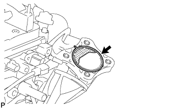
  1. A124566
    Remove the gasket from the intake manifold.


17. DISCONNECT FUEL TUBE SUB-ASSEMBLY

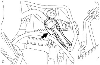
  1. A136015E01
    Remove the No. 1 fuel pipe clamp.

    NOTICE:
    Check for foreign matter on the pipe and around the connector before disconnecting the quick connector. Clean the connector if necessary.

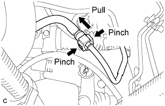
  1. A136016E01
    If the connector and pipe are stuck, pinch the connector, and push and pull the pipe to disconnect them.

    NOTICE:
    1. Do not use any tools in this procedure.
    2. Check for foreign matter on the sealing surface of the disconnected pipe. Clean it if necessary.

  1. A136017E01
    Separate the fuel tube sub-assembly from the fuel hose clamp.


18. REMOVE FUEL DELIVERY PIPE WITH INJECTOR

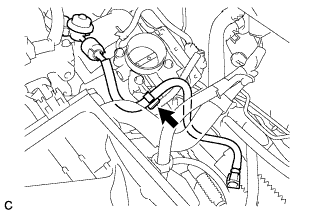
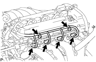
  1. A147100
    Remove the 2 wire harness clamps.

  1. Disconnect the 4 fuel injector connectors.

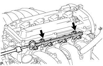
  1. A147099
    Remove the 2 bolts, then remove the fuel delivery pipe together with the 4 fuel injectors.

    NOTICE:
    Be careful not to drop the fuel injectors when removing the fuel delivery pipe.

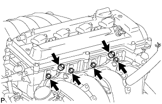
  1. A147098
    Remove the 2 delivery pipe spacers from the cylinder head.

  1. Remove the 4 insulators from the cylinder head.


19. REMOVE INTAKE MANIFOLD
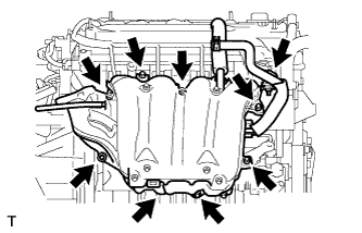
  1. Disconnect the union to check valve hose from the brake booster.

  1. A135672
    Disconnect the camshaft timing oil control valve connector.

  1. Remove the wire harness clamp.

  1. Remove the union to check valve hose from the vacuum hose clamp.

  1. Remove the 5 bolts, 2 nuts and intake manifold.

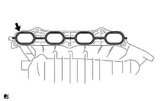
  1. A090130E01
    Remove the gasket from the intake manifold.


20. REMOVE NO. 1 INTAKE MANIFOLD INSULATOR

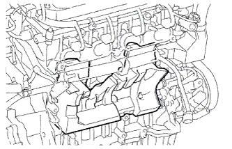
  1. A134343
    Remove the intake manifold insulator from the cylinder block.


21. REMOVE FRONT EXHAUST PIPE ASSEMBLY

HINT:
Click here.


22. REMOVE NO. 2 ENGINE MOUNTING STAY RH

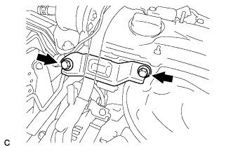
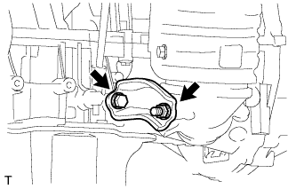
  1. A134912
    Remove the 2 bolts and No. 2 engine mounting stay RH.


23. REMOVE ENGINE MOVING CONTROL ROD SUB-ASSEMBLY

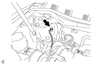
  1. A134909
    Remove the bolt and disconnect the ground cable.

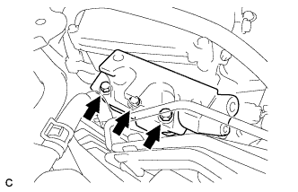
  1. A134910
    Remove the 3 bolts and the engine moving control rod sub-assembly.


24. REMOVE NO. 2 ENGINE MOUNTING BRACKET RH

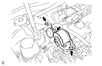
  1. A134911
    Remove the 3 bolts and No. 2 engine mounting bracket RH.


25. REMOVE V-RIBBED BELT

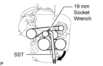
  1. A114351E03
    Using SST and a 19 mm socket wrench, loosen the V-ribbed belt tensioner arm clockwise, then remove the V-ribbed belt.
    SST
    09216-42010  

    NOTICE:
    1. Be sure to connect SST and the tools so that they are in line during use.
    2. When retracting the tensioner, turn it clockwise slowly for 3 seconds or more. Do not apply force rapidly.
    3. After the tensioner is fully retracted, do not apply more force than necessary.


26. REMOVE GENERATOR ASSEMBLY

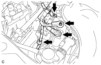
  1. A135170
    Disconnect the generator connector.

  1. Remove the nut and disconnect the wire harness from terminal B.

  1. Remove the bolt and wire harness clamp bracket.

  1. Remove the wire harness clamp.

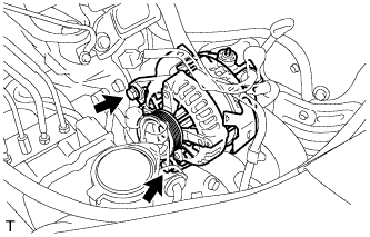
  1. A142104
    Remove the 2 bolts and generator assembly.


27. REMOVE OIL LEVEL GAUGE SUB-ASSEMBLY

28. REMOVE OIL LEVEL GAUGE GUIDE

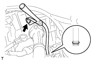
  1. A112218
    Remove the bolt and oil level gauge guide.

  1. Remove the O-ring from the oil level gauge guide.


29. REMOVE MANIFOLD STAY

  1. A112193
    Remove the bolt, nut and stay.


30. REMOVE NO. 2 MANIFOLD STAY

  1. A112192
    Remove the bolt, nut and stay.


31. REMOVE EXHAUST MANIFOLD CONVERTER SUB-ASSEMBLY

  1. A112189
    Remove the 4 bolts and No. 1 insulator.

  1. A098744E01
    Disconnect the air-fuel ratio sensor connector.

  1. A112190
    Remove the 5 nuts, manifold converter and gasket.


32. REMOVE CHAIN SUB-ASSEMBLY

HINT:
Click here.


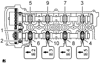
33. REMOVE NO. 2 CAMSHAFT

  1. A098174E11
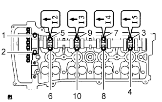
    Using several steps, uniformly loosen and remove the 10 bearing cap bolts in the sequence shown in the illustration.

  1. Remove the 5 bearing caps and No. 2 camshaft.


34. REMOVE CAMSHAFT

  1. A098175E04
    Using several steps, uniformly loosen and remove the 10 bearing cap bolts in the sequence shown in the illustration.

  1. Remove the 5 bearing caps and camshaft.


35. REMOVE CAMSHAFT TIMING OIL CONTROL VALVE ASSEMBLY

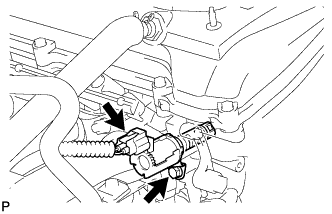
  1. A124556
    Disconnect the camshaft timing oil control valve assembly connector.

  1. Remove the bolt and camshaft timing oil control valve assembly.


36. DISCONNECT RADIATOR HOSE INLET

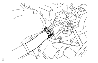
  1. A134907
    Remove the clamp and disconnect the radiator hose inlet.


37. DISCONNECT HEATER WATER HOSE INLET

38. DISCONNECT ENGINE WIRE

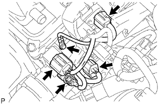
  1. A098748E01
    Disconnect the radio setting condenser connector.

  1. Disconnect the engine oil pressure switch connector.

  1. Disconnect the engine coolant temperature sensor connector.

  1. Disconnect the camshaft position sensor connector.

  1. Remove the bolt and ground cable.


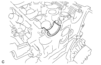
39. REMOVE NO. 2 CAMSHAFT BEARING

  1. A128879
    Remove the No. 2 camshaft bearing.


40. REMOVE CYLINDER HEAD SUB-ASSEMBLY

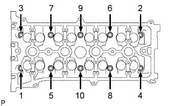
  1. F050595E04
    Using several steps, uniformly loosen and remove the 10 cylinder head set bolts and 10 plate washers with a 10 mm bi-hexagon wrench in the sequence shown in the illustration.

    NOTICE:
    Head warpage or cracking could result from removing the bolts in the wrong order.

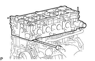
  1. A126930
    Using a screwdriver with its tip wrapped with tape, pry between the cylinder head and cylinder block, and remove the cylinder head.

    NOTICE:
    Be careful not to damage the contact surfaces of the cylinder head and cylinder block.


41. REMOVE CYLINDER HEAD GASKET
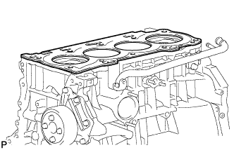
  1. A126929
    Remove the cylinder head gasket.

← COMPONENTS (from Jun 2006)REMOVAL (Oct 2006 – May 2009) →