Throttle Body
Engine Control System
COMPONENTS
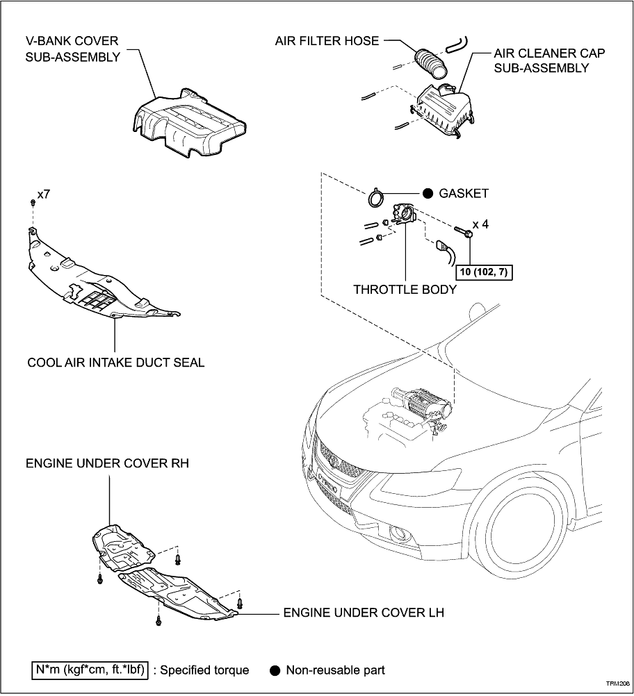
ON-VEHICLE INSPECTION
1. INSPECT THROTTLE BODY
(a) Inspect the throttle control motor for operating sounds.
(1) Turn the engine switch on (IG).
(2) When turning the accelerator pedal position sensor lever, check for running sounds of the motor. The motor should be running smoothly without friction sounds.
If operation is not as specified, check the throttle control motor, wiring and ECM (
Click Here
)
-
(b) Inspect the throttle position sensor.
(1) Connect the intelligent tester to the DLC3.
(2) Turn the engine switch on (IG).
(3) Check the MIL is off.
(4) Check that, under the CURRENT DATA, THROTTLE POS (throttle valve opening percentage) is within the standard range below.
Standard throttle valve opening percentage:
60% or more
If operation is not as specified, check the throttle position sensor, wiring and ECM (
Click Here
)
-
REMOVAL
1. REMOVE ENGINE UNDER COVER RH
2. REMOVE ENGINE UNDER COVER LH
3. REMOVE COOL AIR INTAKE DUCT SEAL (
Click Here
)
4. REMOVE V-BANK COVER SUB-ASSEMBLY (
Click Here
)
5. DRAIN ENGINE COOLANT (
Click Here
)
6. REMOVE AIR CLEANER CAP SUB-ASSEMBLY (
Click Here
)
7. DISCONNECT VACUUM HOSES
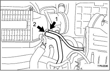
(a) Disconnect the air cleaner cap vacuum hose (1).
-
(b) Disconnect the vacuum switching valve hose (2).
-
8. REMOVE THROTTLE BODY
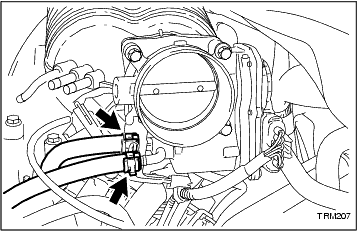
(a) Disconnect the 2 water by-pass hoses from the throttle body.
-
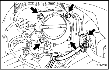
(b) Disconnect the wire connector.
-
(c) Remove the 4 bolts and the throttle body.
-
(d) Remove the throttle body gasket from the supercharger.
-
INSPECTION
1. INSPECT THROTTLE BODY ASSEMBLY
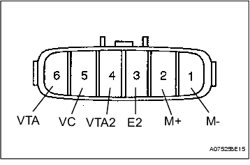
INSTALLATION
1. INSTALL THROTTLE BODY
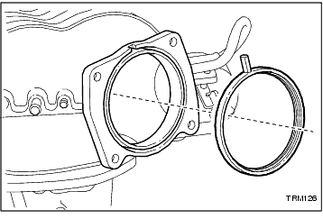
(a) Install a new throttle body gasket to the supercharger.
-
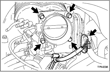
(b) Install the throttle body with the 4 bolts.
Torque:
10 N*m
(102 kgf*cm,
7 ft.*lbf)
-
(c) Connect the wire connector.
-
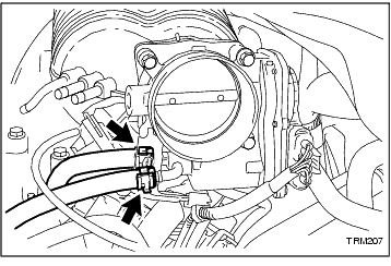
(d) Connect the 2 water by-pass hoses.
-
2. CONNECT VACUUM HOSES
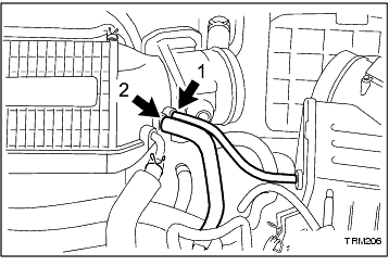
(a) Connect the air cleaner cap vacuum hose (1).
-
(b) Connect the vacuum switching valve hose (2).
-
3. INSTALL AIR CLEANER CAP SUB-ASSEMBLY (
Click Here
)
4. ADD ENGINE COOLANT (
Click Here
)
5. INSPECT FOR COOLANT LEAK (
Click Here
)
6. CHECK FUNCTION OF THROTTLE BODY (
Click Here
)
7. INSTALL V-BANK COVER SUB-ASSEMBLY (
Click Here
)
8. INSTALL COOL AIR INTAKE DUCT SEAL (
Click Here
)
9. INSTALL ENGINE UNDER COVER LH
10. INSTALL ENGINE UNDER COVER RH