Drive Belt Tensioner & Pulleys
Engine Mechanical
COMPONENTS
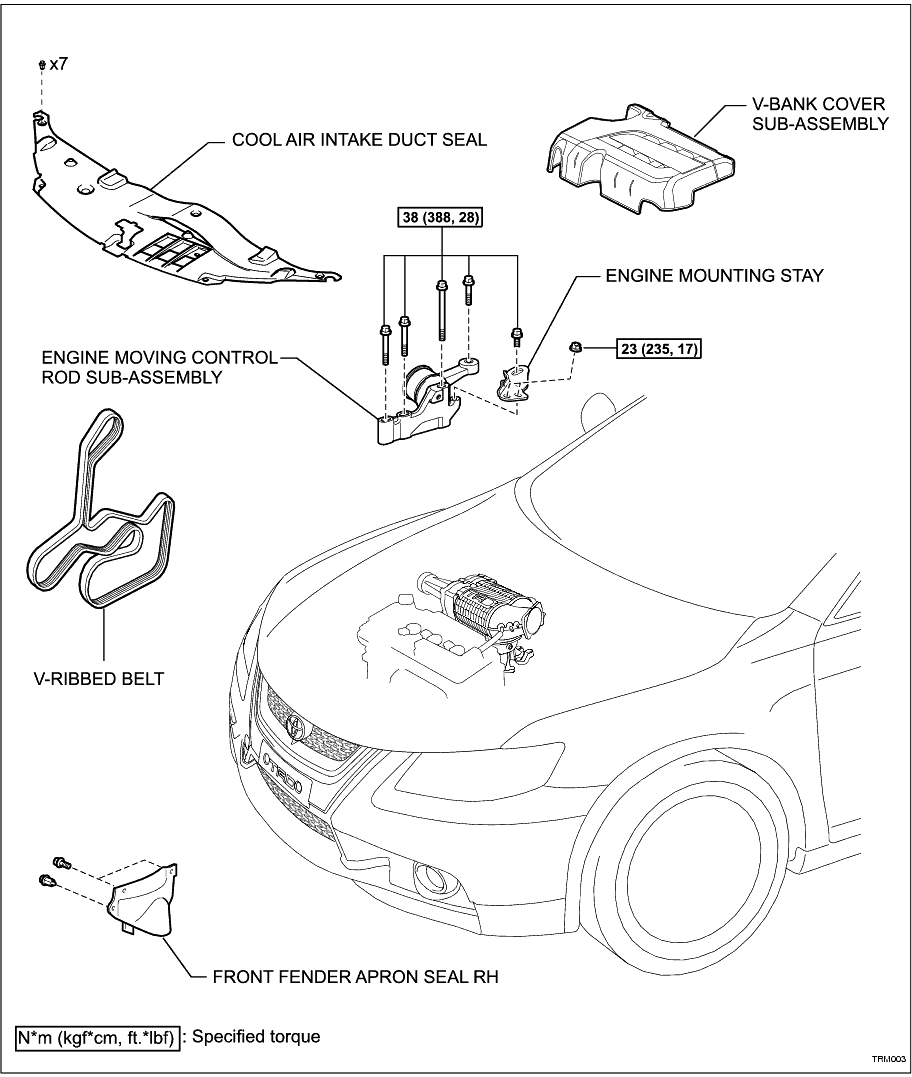
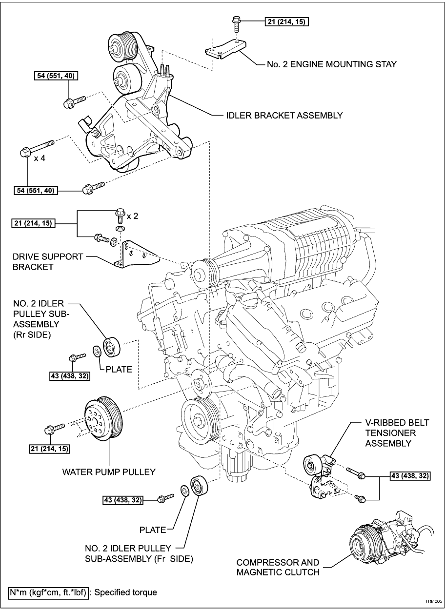
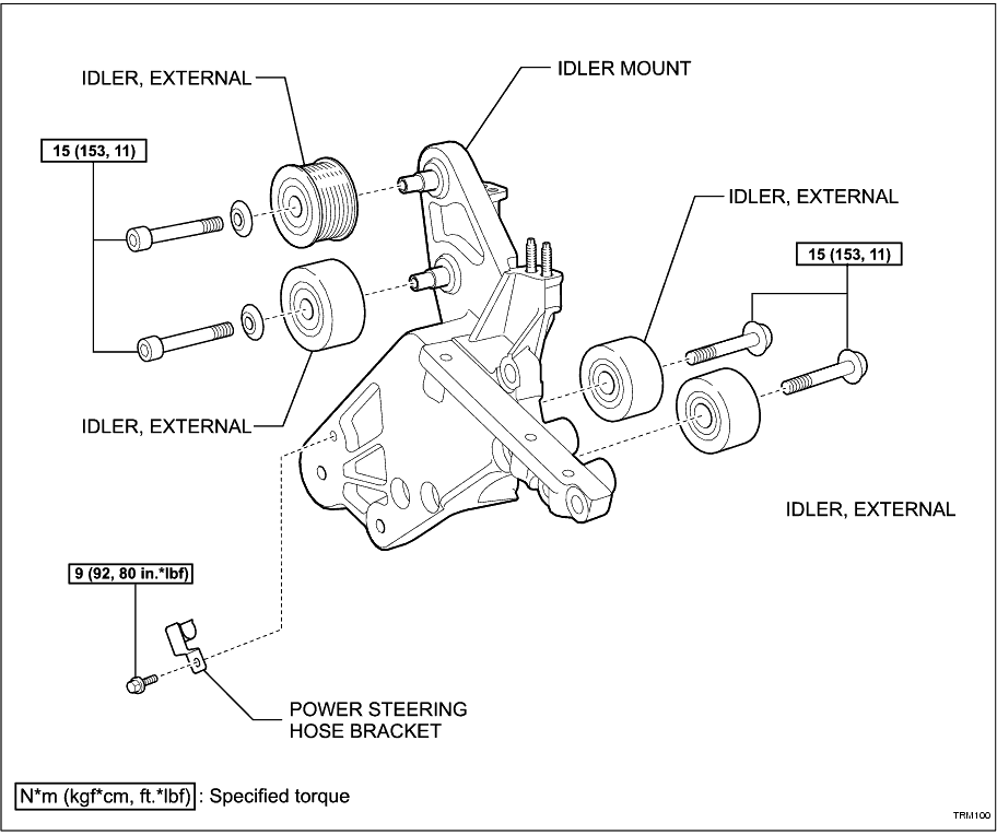
REMOVAL
1. DISCONNECT CABLE FROM NEGATIVE BATTERY TERMINAL
2. PLACE FRONT WHEELS FACING STRAIGHT AHEAD
3. REMOVE FRONT WHEEL RH
4. REMOVE FRONT FENDER APRON SEAL RH
5. REMOVE COOL AIR INTAKE DUCT SEAL (
Click Here
)
6. REMOVE V-BANK COVER SUB-ASSEMBLY (
Click Here
)
7. REMOVE ENGINE MOUNTING STAY (
Click Here
)
8. REMOVE ENGINE MOVING CONTROL ROD SUB-ASSEMBLY (
Click Here
)
9. REMOVE V-RIBBED BELT (
Click Here
)
10. RAISE ENGINE
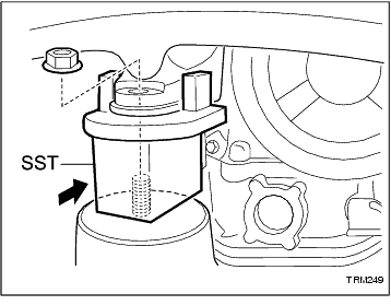
(a) Remove the rear right-hand engine mount nut.
-
(b) Position a trolley jack with an engine cradle beneath the right-hand side of the engine.
-
(c) Carefully raise the engine until the SST can be fitted between the engine mount and engine mounting bracket.
SST
SR-1146
-
(d) Carefully lower the trolley jack and remove.
-
11. REMOVE IDLER BRACKET ASSEMBLY
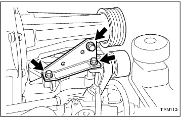
(a) Remove the 3 bolts and the drive support bracket.
-
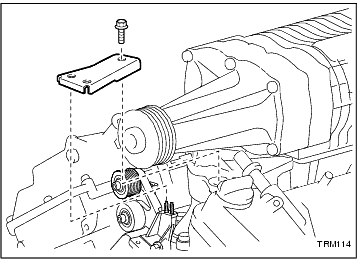
(b) Remove the bolt and the No. 2 engine mounting stay.
-
(c) Unattach the power steering hose from the bracket.
-
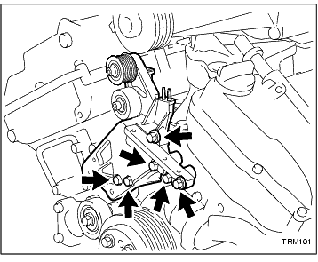
(d) Remove the 6 bolts and the idler bracket assembly.
HINT:
The lower bolts cannot be completely removed until the idler bracket assembly has been removed.
-
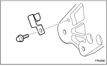
(e) Remove the bolt and remove the power steering hose bracket.
-
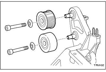
(f) Remove the 2 bolts and washers, and remove the internal idler pulleys.
-
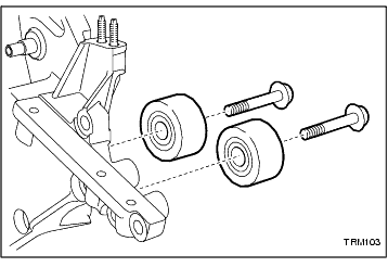
(g) Remove the 2 bolts and remove the internal idler pulleys.
-
12. REMOVE V-RIBBED BELT TENSIONER ASSEMBLY
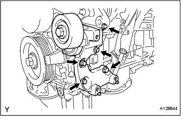
(a) Separate the compressor and magnetic clutch from the engine. (
Click Here
)
HINT:
Do not discharge the refrigerant or remove the refrigerant hoses. Secure the compressor and magnetic clutch to one side.
-
(b) Remove the 5 bolts and V-ribbed belt tensioner assembly.
-
13. REMOVE NO. 2 IDLER PULLEY SUB-ASSEMBLY
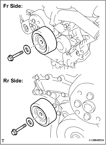
(a) Remove the bolts, plates and No. 2 idler pulley sub-assemblies.
-
14. REMOVE WATER PUMP PULLEY
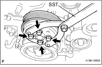
(a) Using SST, hold the water pump pulley.
SST
09960-10010
(09962-01000
09963-00700)
-
(b) Remove the 4 bolts and water pump pulley.
-
INSTALLATION
1. INSTALL WATER PUMP PULLEY
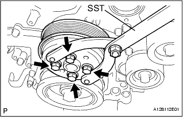
(a) Temporarily install the water pump pulley with the 4 bolts.
-
(b) Using SST, hold the water pump pulley.
SST
09960-10010
(09962-01000
09963-00700)
-
(c) Tighten the 4 bolts.
Torque:
21 N*m
(214 kgf*cm,
15 ft.*lbf)
-
2. INSTALL NO. 2 IDLER PULLEY SUB-ASSEMBLY
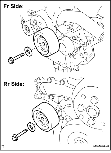
(a) Install the No. 2 idler pulley sub-assemblies and cover plates with the bolts.
Torque:
43 N*m
(438 kgf*cm,
32 ft.*lbf)
-
3. INSTALL V-RIBBED BELT TENSIONER ASSEMBLY
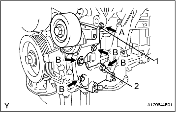
(a) Temporarily install the V-ribbed belt tensioner with the 5 bolts.
HINT:
Bolt length:
A: 70 mm (2.76 in.)
B: 33 mm (1.30 in.)
-
(b) Install the V-ribbed belt tensioner by tightening the bolt 1 and bolt 2 in the order shown in the illustration.
Torque:
43 N*m
(438 kgf*cm,
32 ft.*lbf)
-
(c) Tighten the other bolts.
Torque:
43 N*m
(438 kgf*cm,
32 ft.*lbf)
-
4. INSTALL IDLER BRACKET ASSEMBLY
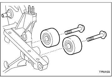
(a) Install the internal idler pulleys and the 2 bolts.
Torque:
15 N*m
(153 kgf*cm,
11 ft.*lbf)
-
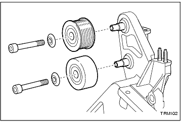
(b) Install the internal idler pulleys and the 2 bolts and washers.
Torque:
15 N*m
(153 kgf*cm,
11 ft.*lbf)
-
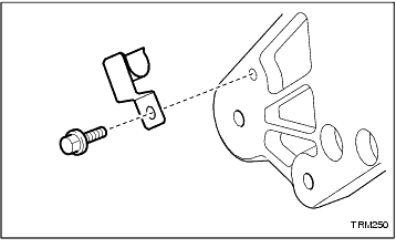
(c) Install the power steering hose bracket with the bolt.
Torque:
9 N*m
(92 kgf*cm,
80 in.*lbf)
-
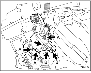
(d) Install the idler bracket assembly.
(1) Fit a long bolt into the lower idler bracket bolt hole and partially lower the bracket assembly between the engine and body.
HINT:
Bolt length:
A: 115 mm (4.52 in.)
(2) Fit another long bolt into the next lower idler bracket bolt hole and fully lower the bracket assembly in to position.
(3) Hand tighten these bolts.
(4) Fit the 2 remaining long bolts and 2 short bolts and hand tighten.
HINT:
Bolt length:
B: 45 mm (1.77 in.)
-
(e) Tighten the 6 bolts.
Torque:
54 N*m
(551 kgf*cm,
40 ft.*lbf)
-
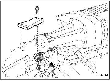
(f) Install the No. 2 engine mounting stay with the bolt.
Torque:
21 N*m
(214 kgf*cm,
15 ft.*lbf)
-
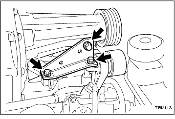
(g) Install the drive support bracket with the 3 bolts.
Torque:
21 N*m
(214 kgf*cm,
15 ft.*lbf)
-
5. LOWER ENGINE
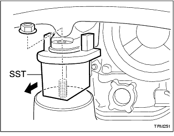
(a) Position a trolley jack with an engine cradle beneath the right-hand side of the engine.
-
(b) Carefully raise the engine until the SST can be removed from between the rear right-hand engine mount and engine mounting bracket.
SST
SR-1146
-
(c) Carefully lower the trolley jack and remove.
-
(d) Install the engine mount nut.
Torque:
95 N*m
(969 kgf*cm,
64 ft.*lbf)
-
6. INSTALL V-RIBBED BELT (
Click Here
)
7. INSTALL ENGINE MOVING CONTROL ROD SUB-ASSEMBLY (
Click Here
)
8. INSTALL ENGINE MOUNTING STAY (
Click Here
)
9. INSTALL V-BANK COVER SUB-ASSEMBLY (
Click Here
)
10. INSTALL COOL AIR INTAKE DUCT SEAL (
Click Here
)
11. INSTALL FRONT FENDER APRON SEAL RH
12. INSTALL FRONT WHEEL RH
13. CONNECT CABLE TO NEGATIVE BATTERY TERMINAL