Parking Brake Assembly
Parking Brake
COMPONENTS
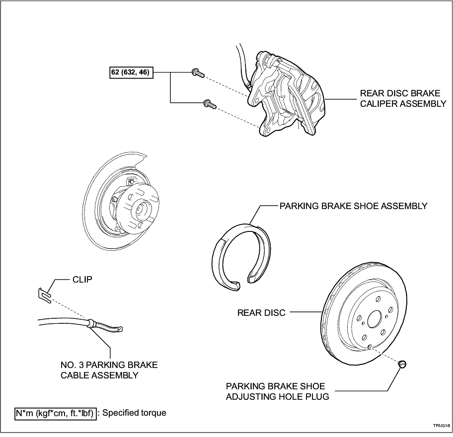
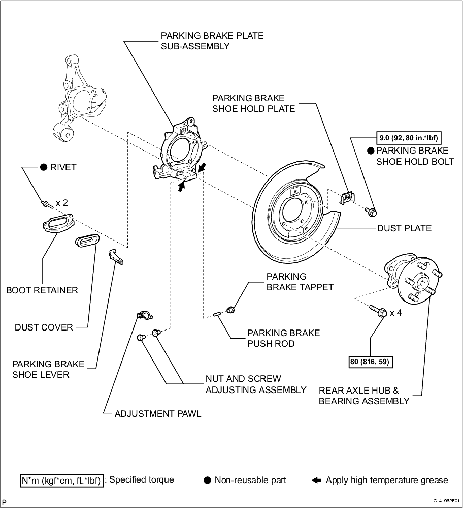
DISASSEMBLY
HINT:
• Use the same procedures for the RH side and the LH side.
• The procedures listed below are for the LH side.
1. REMOVE REAR WHEEL
2. SEPARATE REAR DISC BRAKE CALIPER ASSEMBLY
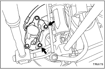
(a) Remove the 2 bolts and separate the rear disc brake caliper assembly.
HINT:
• Do not disconnect the flexible hose.
• Do not remove the brake pads.
• Do not allow the brake caliper to hang on the flexible hose. Always support the brake caliper.
-
3. REMOVE REAR DISC
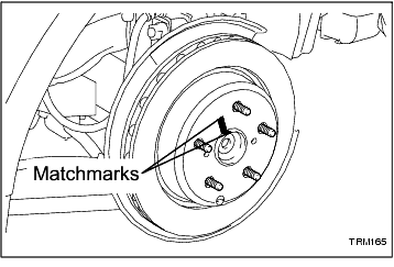
(a) Release the parking brake and put matchmarks on the rear disc and the axle hub.
-
(b) Remove the rear disc.
HINT:
• If the rear disc is difficult to remove, rotate the disc while removing.
• If the rear disc jams, return the disc to its original position, remove the adjusting hole plug and turn the shoe adjusting nut in the clockwise direction to contract the parking brake shoe.
-
4. REMOVE PARKING BRAKE SHOE ASSEMBLY
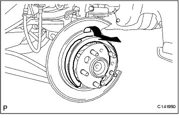
(a) Remove the parking brake shoe assembly as shown in the illustration.
-
5. DISCONNECT NO. 3 PARKING BRAKE CABLE ASSEMBLY
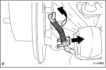
(a) Using needle-nose pliers, remove the clip.
-
(b) Turn and disconnect the No. 3 parking brake cable assembly as shown in the illustration.
-
6. REMOVE REAR AXLE HUB AND BEARING ASSEMBLY
(a) Disconnect the VSC sensor connector.
-
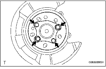
(b) Remove the 4 bolts and hub and bearing assembly.
-
7. REMOVE PARKING BRAKE PLATE SUB-ASSEMBLY
8. REMOVE NUT AND SCREW ADJUSTING ASSEMBLY
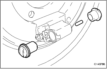
(a) Remove the nut and screw adjusting assembly, parking brake tappet and parking brake push rod.
-
9. REMOVE ADJUSTMENT PAWL
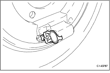
(a) Remove the adjustment pawl.
-
10. REMOVE PARKING BRAKE SHOE HOLD PLATE
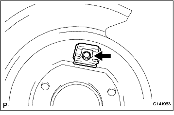
(a) Remove the parking brake shoe hold bolt and the parking brake shoe hold plate.
-
11. SEPARATE DUST PLATE
(a) Separate the dust plate from the parking brake plate sub-assembly.
-
12. REMOVE DUST COVER
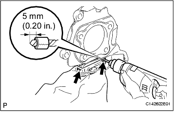
(a) Insert a 4 mm (0.16 in.) drill bit into a drill.
-
(b) Tape the drill bit leaving 5 mm (0.20 in.) from the tip uncovered.
HINT:
Tape the drill bit to prevent drilling too deep.
-
(c) Lightly press the drill against the rivets, drill off the flanges of the rivets, and remove the 2 rivets.
NOTICE:
• Cover the dust cover with a piece of cloth to prevent rivet fragments and shavings from scattering.
• Pressing the drill too firmly will cause the rivet to turn and result in the rivet not being drilled through.
• Do not drill the rivet at an angle as this will cause damage to the drill and drill hole. Line up the drill and rivet, and carefully drill out the rivet head.
• Be careful as the cut rivet will be very hot.
-
(d) Remove the boot retainer and the dust cover.
-
(e) Even if the flange is taken off, continue to drill the rivet and push out the remaining fragment using a drill.
-
(f) Using a vacuum cleaner, remove the rivet fragments and shavings.
-
13. REMOVE PARKING BRAKE SHOE LEVER
INSPECTION
1. INSPECT BRAKE DISC INSIDE DIAMETER
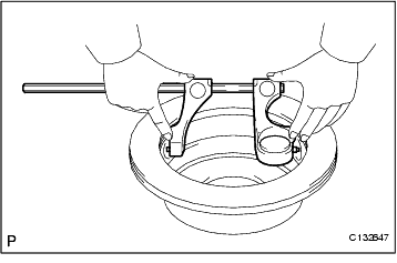
(a) Using a brake drum gauge or an equivalent tool, measure the inside diameter of the disc.
Standard inside diameter:
190 mm (7.48 in.)
Maximum inside diameter:
191 mm (7.52 in.)
If the inside diameter is more than the maximum, replace the disc.
-
2. INSPECT PARKING BRAKE SHOE LINING THICKNESS
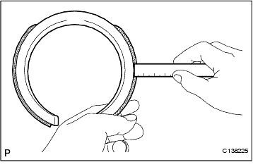
(a) Using a ruler, measure the thickness of the parking brake shoe lining.
Standard thickness:
3.8 mm (0.150 in.)
Minimum thickness:
1.0 mm (0.039 in.)
-
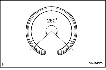
(b) Using a ruler, measure the thickness variation within the 260? range as shown in the illustration.
Thickness variation within 260? range:
0.5 mm (0.05 in.) or less.
If the lining thickness is less than the minimum, or if there is severe or uneven wear, replace the parking brake shoe.
NOTICE:
Always replace both the right and left parking brake shoes together.
-
3. INSPECT BRAKE DISC AND PARKING BRAKE SHOE LINING FOR CONTACT
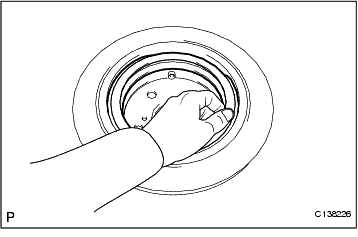
(a) Apply chalk to the inside surface of the disc and fit the parking brake shoe.
If the contact between the disc and the parking brake shoe lining is uneven, repair it using a brake shoe grinder or replace the parking brake shoe.
-
REASSEMBLY
1. INSTALL PARKING BRAKE SHOE LEVER
2. INSTALL DUST COVER
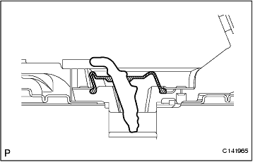
(a) Install the dust cover to the parking brake shoe lever as shown in the illustration.
-
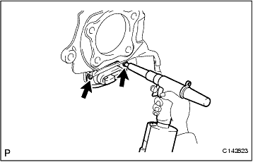
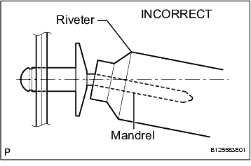
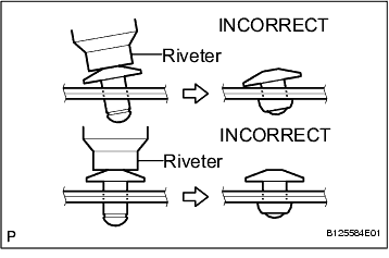
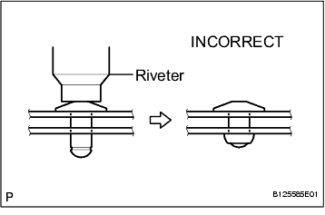
(b) Using an air or hand riveter with a nose piece, install the boot retainer on the back plate with 2 new rivets.
HINT:
If the rivet cannot be cut, pull it once and cut it.
NOTICE:
• Do not prise the rivet with the riveter, as this will cause damage to the riveter and mandrel.
• Confirm the rivets are seated correctly against the boot retainer. Do not tilt the riveter when installing the rivet to the boot retainer. Do not leave any space between the rivet head and the boot retainer.
• Do not leave any space between the boot retainer and the back plate. Firmly hold together the 2 items while installing the rivet.
-
3. INSTALL DUST PLATE
(a) Install the dust plate to the parking brake plate sub-assembly.
-
4. INSTALL PARKING BRAKE SHOE HOLD PLATE
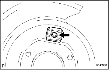
(a) Install the parking brake shoe hold plate with a new parking brake shoe hold bolt.
Torque:
9.0 N*m
(92 kgf*cm,
80 in.*lbf)
-
5. INSTALL ADJUSTMENT PAWL
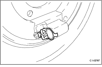
(a) Install the adjustment pawl.
-
6. INSTALL NUT AND SCREW ADJUSTING ASSEMBLY
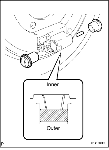
(a) Apply high temperature grease to the inside of the back plate bore as shown in the illustration.
-
(b) Install the nut and screw adjusting assembly, parking brake tappet and parking brake push rod.
-
7. INSTALL PARKING BRAKE PLATE SUB-ASSEMBLY
8. INSTALL REAR AXLE HUB AND BEARING ASSEMBLY
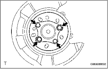
(a) Install the hub and bearing assembly with the 4 bolts.
Torque:
80 N*m
(816 kgf*cm,
59 ft.*lbf)
-
(b) Connect the VSC sensor connector.
NOTICE:
Do not twist the sensor wire when connecting it.
-
9. CONNECT NO. 3 PARKING BRAKE CABLE ASSEMBLY
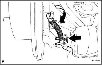
(a) Turn and connect the No. 3 parking brake cable assembly.
-
(b) Using a brass bar and a hammer, install the clip to the No. 3 parking brake cable assembly.
-
10. INSTALL PARKING BRAKE SHOE ASSEMBLY
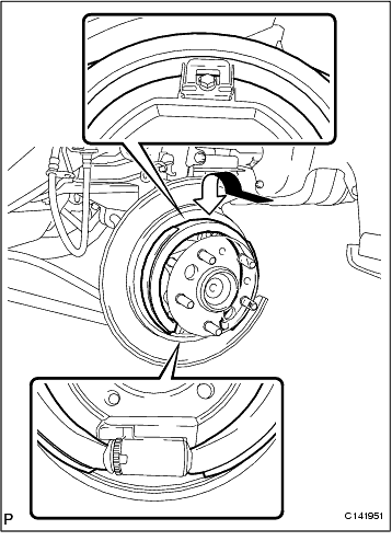
(a) Install the parking brake shoe assembly as shown in the illustration.
NOTICE:
There should be no oil or grease on the friction surface of the lining and disc.
-
11. INSPECT REAR AXLE HUB BEARING LOOSENESS (
Click Here
)
12. INSPECT REAR AXLE HUB RUNOUT (
Click Here
)
13. INSPECT PARKING BRAKE SHOE DIAMETER (
Click Here
)
14. ADJUST PARKING BRAKE SHOE DIAMETER (
Click Here
)
15. INSTALL REAR DISC
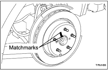
(a) Align the matchmarks and install the rear disc.
-
(b) Install the adjusting hole plug, if removed.
-
16. INPSECT FOR PARKING BRAKE SHOE DRAG (
Click Here
)
17. INSTALL REAR DISC BRAKE CALIPER ASSEMBLY
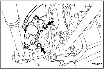
(a) Install the rear disc brake caliper assembly with the 2 bolts.
Torque:
62 N*m
(632 kgf*cm,
46 ft.*lbf)
-
18. INSTALL REAR WHEEL
19. INSPECT PARKING BRAKE PEDAL TRAVEL (
Click Here
)
20. ADJUST PARKING BRAKE PEDAL TRAVEL (
Click Here
)
21. INSPECT VSC SENSOR SIGNAL (
Click Here
)