Front Bumper
Exterior
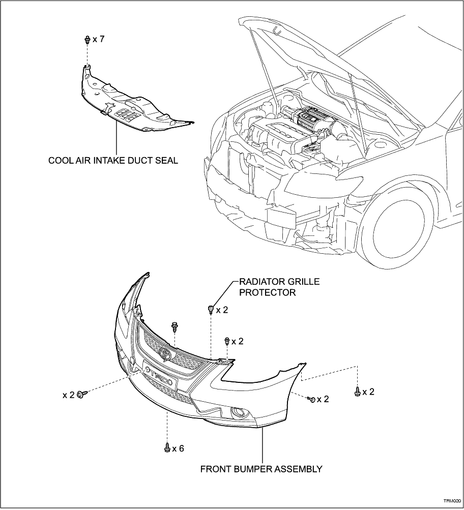
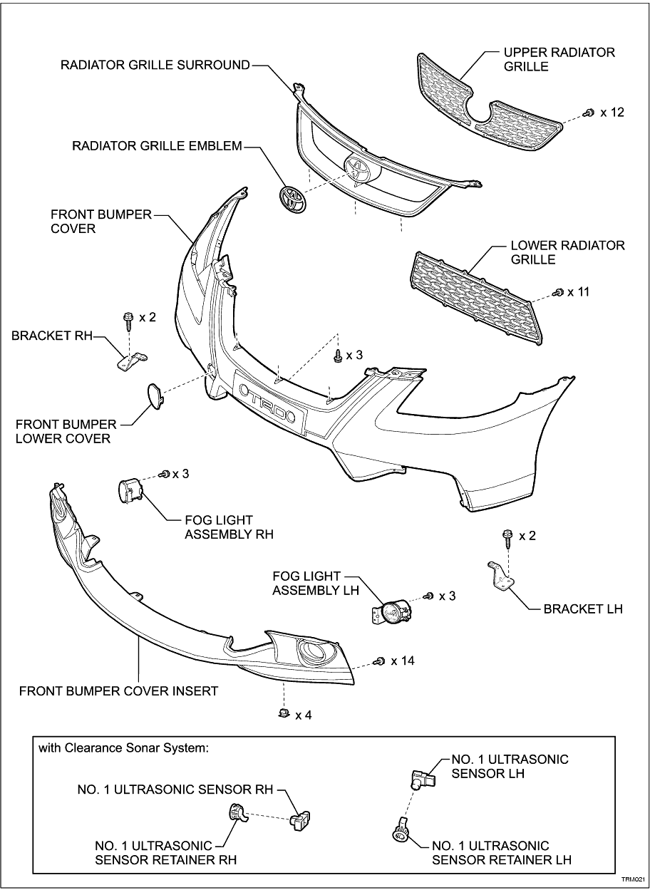
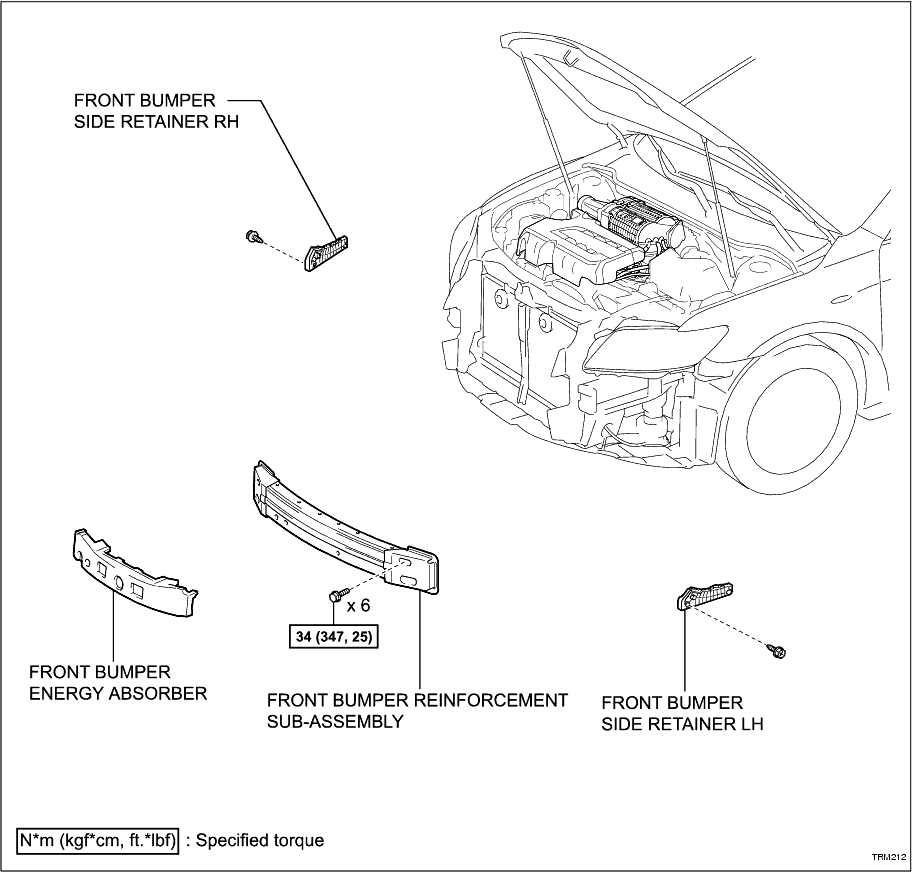
COMPONENTS
REMOVAL
1. REMOVE COOL AIR INTAKE DUCT SEAL
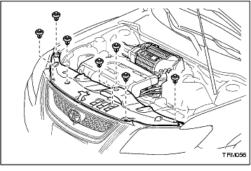
(a) Remove the 7 clips and cool air intake duct seal.
-
2. REMOVE FRONT BUMPER ASSEMBLY
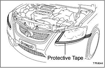
(a) Put protective tape around the front bumper assembly.
-
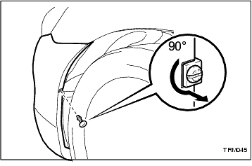
(b) Using a screwdriver, turn the pin 90 degrees and remove the pin hold clip.
HINT:
Use the same procedure for the RH side and LH side.
-
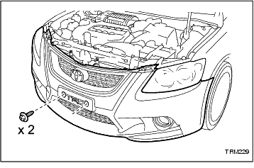
(c) Remove the licence plate, if fitted.
-
(d) Remove the 2 screws.
-
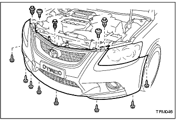
(e) Remove the 8 screws, 3 clips and 2 radiator grille protectors.
-
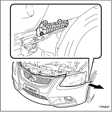
(f) Disengage the 2 claws and disconnect the front bumper assembly as shown in the illustration.
HINT:
Use the same procedure for the RH side and LH side.
-
(g) Disconnect each fog light and clearance sensor (if fitted) connector, and then remove the front bumper assembly.
-
DISASSEMBLY
1. REMOVE NO. 1 ULTRASONIC SENSOR (w/ Clearance Sonar System) (
Click Here
)
2. REMOVE NO. 1 ULTRASONIC SENSOR RETAINER (w/ Clearance Sonar System) (
Click Here
)
3. REMOVE FRONT BUMPER BRACKET LH
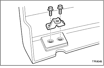
(a) Remove the 2 screws and front bumper bracket LH.
-
4. REMOVE FRONT BUMPER BRACKET RH
5. REMOVE FRONT BUMPER LOWER COVER
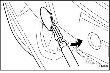
(a) Disengage the claw and remove the front bumper lower cover.
-
6. REMOVE FOG LIGHT ASSEMBLY LH (
Click Here
)
7. REMOVE FOG LIGHT ASSEMBLY RH
8. REMOVE LOWER RADIATOR GRILLE
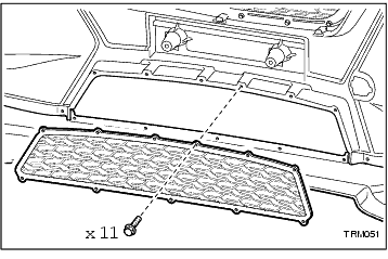
(a) Remove the 11 screws and remove the lower radiator grille.
-
9. REMOVE FRONT BUMPER COVER INSERT
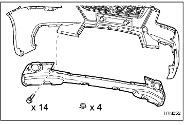
(a) Remove the 14 screws and remove the front bumper cover insert.
-
(b) Remove the 4 screw grommets.
-
10. REMOVE UPPER RADIATOR GRILLE ASSEMBLY
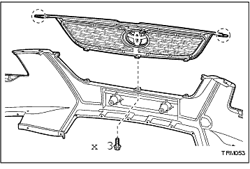
(a) Remove the 3 screws.
-
(b) Disengage the 2 claws and remove the upper radiator grille assembly.
-
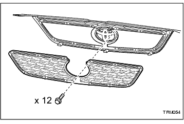
(c) Remove the 12 screws and remove the upper radiator grille.
-
11. REMOVE RADIATOR GRILLE EMBLEM
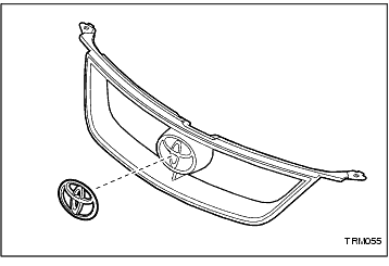
(a) Carefully prise the radiator grille emblem from the radiator grille surround.
-
12. REMOVE FRONT BUMPER ENERGY ABSORBER
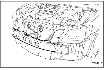
(a) Remove the front bumper energy absorber from the front bumper reinforcement sub-assembly.
-
13. REMOVE FRONT BUMPER REINFORCEMENT SUB-ASSEMBLY
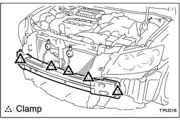
(a) Disengage each clamp.
-
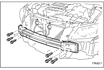
(b) Remove the 6 bolts and front bumper reinforcement sub-assembly.
-
14. REMOVE FRONT BUMPER SIDE RETAINER LH
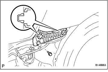
(a) Remove the screw.
-
(b) Disengage the 2 claws and remove the front bumper side retainer LH.
-
15. REMOVE FRONT BUMPER SIDE RETAINER RH
REASSEMBLY
NOTICE:
If a new front bumper cover is being fitted, cut holes for the ultrasonic sensors, if fitted, before painting the new cover. Refer to the installation instructions provided with the new bumper cover.
1. INSTALL FRONT BUMPER SIDE RETAINER LH
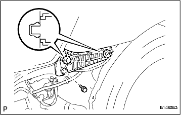
(a) Engage the 2 claws and install the front bumper side retainer LH.
-
(b) Install the screw.
-
2. INSTALL FRONT BUMPER SIDE RETAINER RH
3. INSTALL FRONT BUMPER REINFORCEMENT SUB-ASSEMBLY
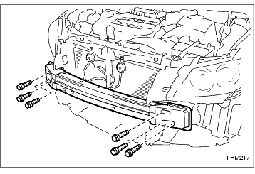
(a) Install the front bumper reinforcement sub-assembly with the 6 bolts.
Torque:
34 N*m
(347 kgf*cm,
25 ft.*lbf)
-
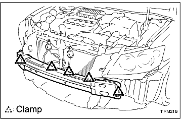
(b) Engage each clamp.
-
4. INSTALL FRONT BUMPER ENERGY ABSORBER
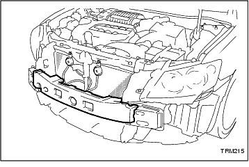
(a) Install the front bumper energy absorber to the front bumper reinforcement sub-assembly.
-
5. INSTALL RADIATOR GRILLE EMBLEM
(a) Clean the radiator grille surface.
(1) Using a heat light, heat the radiator grille surface.
(2) Remove the double-sided tape from the radiator grille.
(3) Wipe off any tape adhesive residue with cleaner.
-
(b) Clean the emblem. (If reusing the emblem)
(1) Using a heat light, heat the emblem.
(2) Remove the double-sided tape from the emblem.
(3) Wipe off any tape adhesive residue with cleaner.
(4) Apply new double-sided tape to the emblem.
-
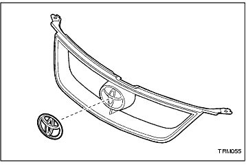
(c) Install the emblem.
(1) Using a heat light, heat the radiator grille and emblem.
(2) Remove the release paper from the emblem.
HINT:
After removing the release paper, keep the exposed adhesive free from foreign matter.
(3) Install the emblem.
-
6. INSTALL UPPER RADIATOR GRILLE ASSEMBLY
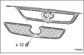
(a) Install the upper radiator grille to the radiator grille surround with the 12 screws.
-
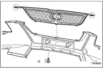
(b) Engage the 2 claws and install the upper radiator grille assembly.
-
(c) Install the 3 screws.
-
7. INSTALL FRONT BUMPER COVER INSERT
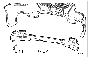
(a) Install the 4 screw grommets.
-
(b) Install the front bumper cover insert with the 14 screws.
-
8. INSTALL LOWER RADIATOR GRILLE
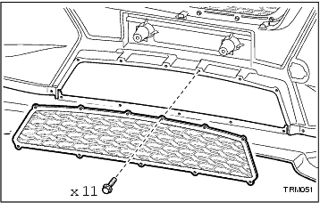
(a) Install the lower radiator grille with the 11 screws.
-
9. INSTALL FOG LIGHT ASSEMBLY LH (
Click Here
)
10. INSTALL FOG LIGHT ASSEMBLY RH
11. INSTALL FRONT BUMPER LOWER COVER
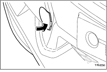
(a) Engage the claw and install the front bumper lower cover.
-
12. INSTALL FRONT BUMPER BRACKET LH
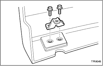
(a) Install the front bumper bracket LH with the 2 screws.
-
13. INSTALL FRONT BUMPER BRACKET RH
14. INSTALL NO. 1 ULTRASONIC SENSOR RETAINER (w/ Clearance Sonar System) (
Click Here
)
15. INSTALL NO. 1 ULTRASONIC SENSOR (w/ Clearance Sonar System) (
Click Here
)
INSTALLATION
1. INSTALL FRONT BUMPER ASSEMBLY
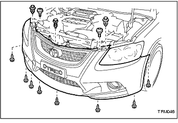
(a) Install the front bumper assembly and connect each fog light and clearance sensor (if fitted) connector.
-
(b) Engage each claw.
-
(c) Install the 8 screws, 3 clips and 2 radiator grille protectors.
-
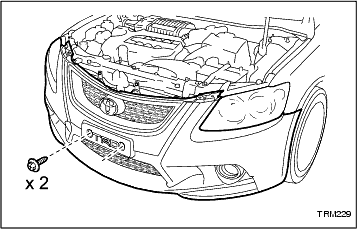
(d) Install the 2 screws.
-
(e) Install the licence plate, if fitted.
-
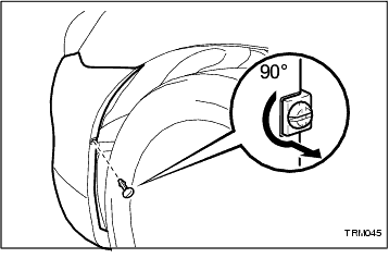
(f) Install the pin hold clip.
HINT:
Use the same procedure for the RH side and LH side.
-
(g) Remove the protective tape.
-
2. INSTALL COOL AIR INTAKE DUCT SEAL
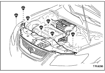
(a) Install the cool air intake duct seal with the 7 clips.
-
3. REMOVE PROTCTIVE TAPE
4. VEHICLE PREPARATION FOR FOG LIGHT AIMING ADJUSTMENT (
Click Here
)
5. PREPARATION FOR FOG LIGHT AIMING (
Click Here
)
6. FOG LIGHT AIMING INSPECTION (
Click Here
)
7. FOG LIGHT AIMING ADJUSTMENT (
Click Here
)