Rear Bumper
Exterior
COMPONENTS
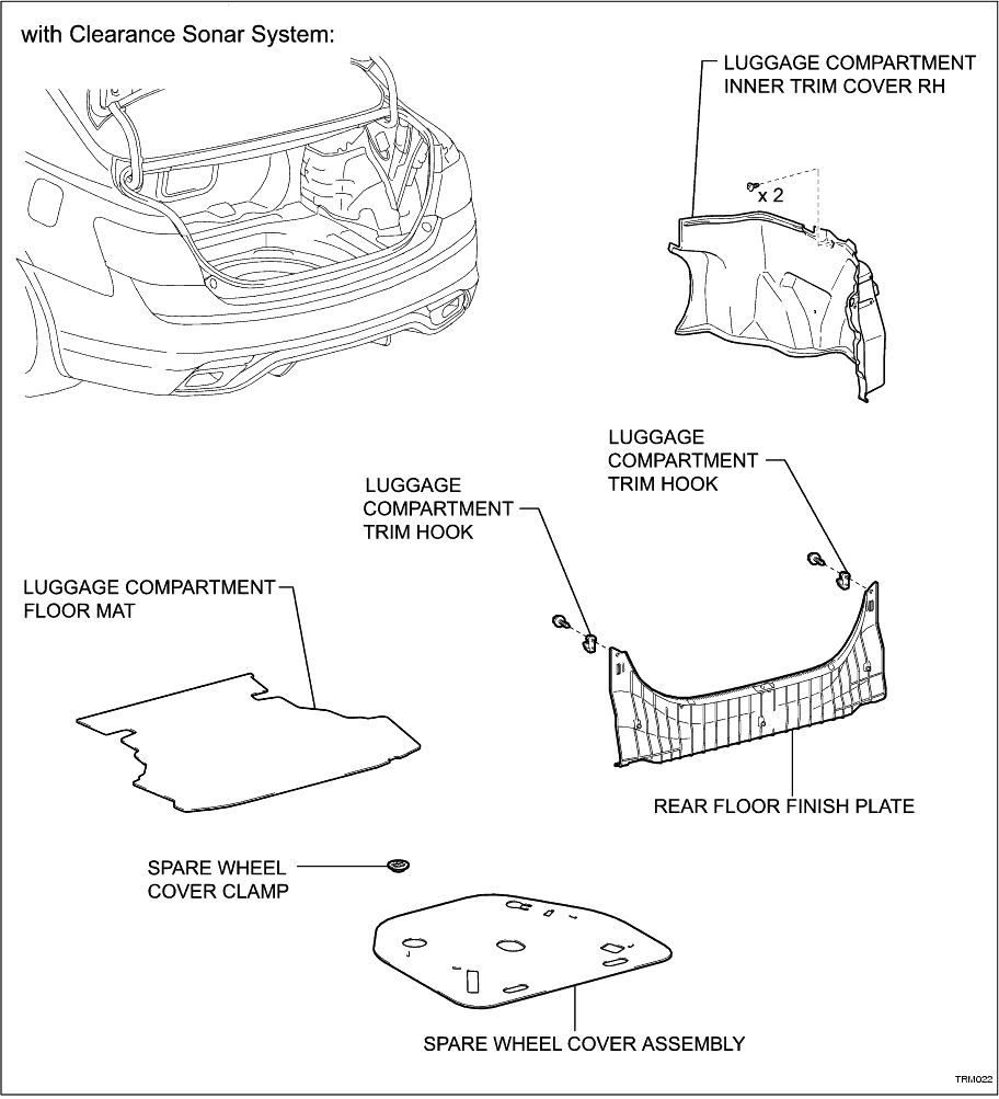
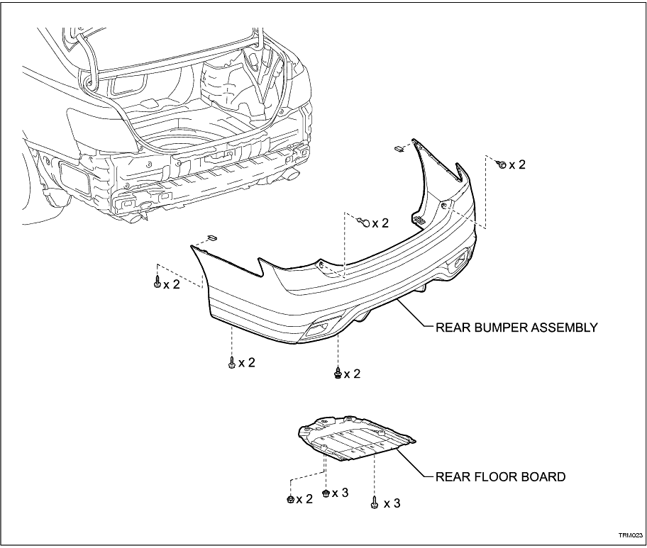
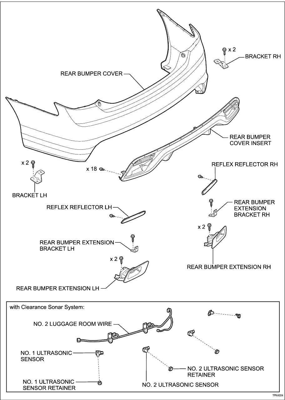
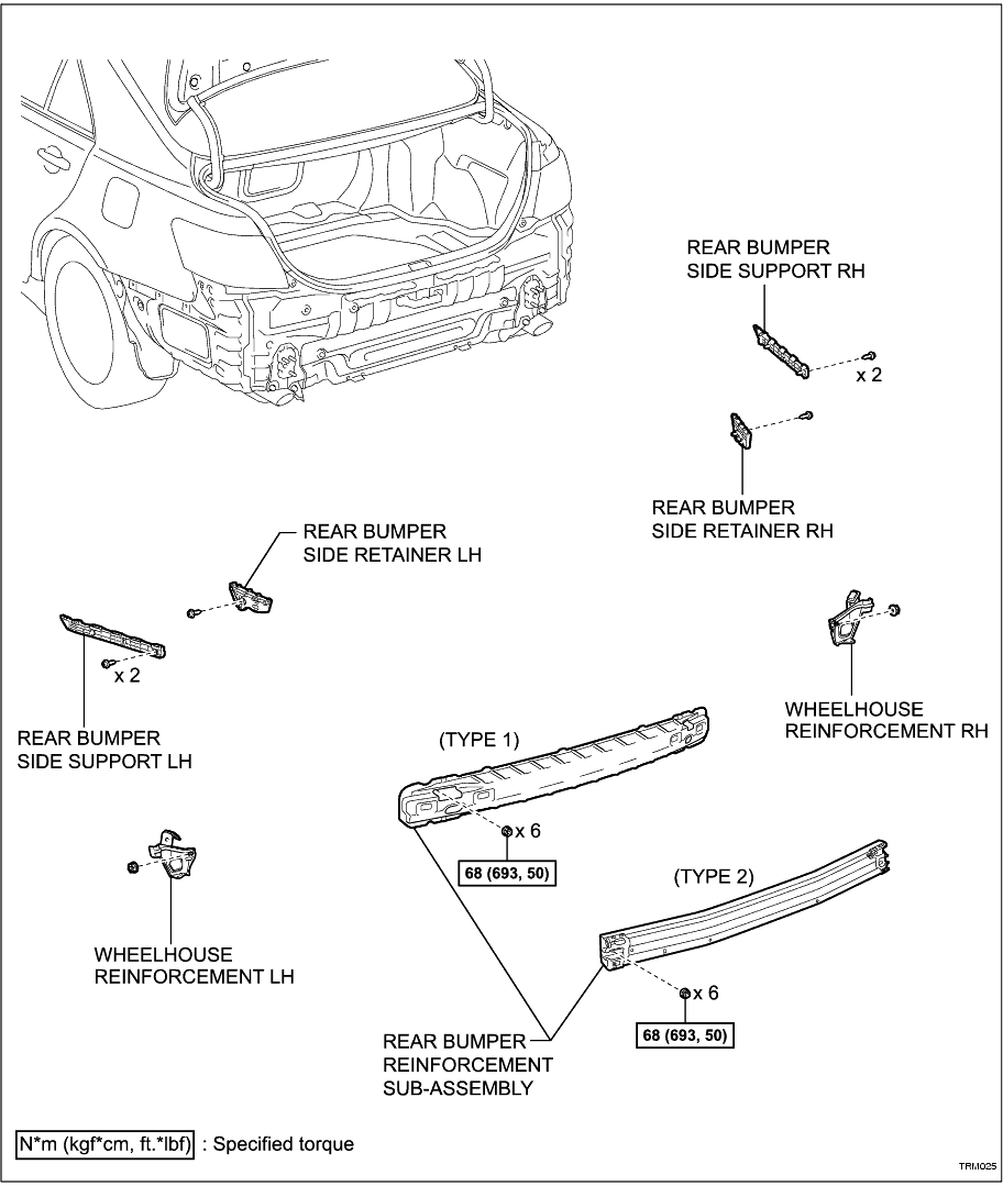
REMOVAL
1. REMOVE REAR FLOOR BOARD
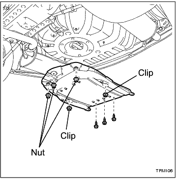
(a) Remove the 3 screws, 2 clips, 3 nuts and rear floor board.
-
2. REMOVE LUGGAGE COMPARTMENT FLOOR MAT (w/ Clearance Sonar System)
3. REMOVE SPARE WHEEL COVER CLAMP (w/ Clearance Sonar System)
4. REMOVE SPARE WHEEL COVER ASSEMBLY (w/ Clearance Sonar System)
5. REMOVE LUGGAGE COMPARTMENT TRIM HOOK (w/ Clearance Sonar System) (
Click Here
)
6. REMOVE REAR FLOOR FINISH PLATE (w/ Clearance Sonar System) (
Click Here
)
7. REMOVE LUGGAGE COMPARTMENT INNER TRIM COVER RH (w/ Clearance Sonar System) (
Click Here
)
8. REMOVE REAR BUMPER ASSEMBLY
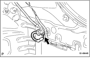
(a) Disconnect the connector (w/ Clearance Sonar System).
-
(b) Disengage the grommet (w/ Clearance Sonar System).
-
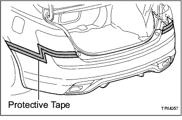
(c) Put protective tape around the rear bumper assembly.
-
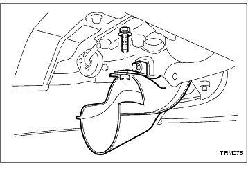
(d) Remove the rear bumper extension bracket screw.
HINT:
Use the same procedure for the RH side and LH side.
-
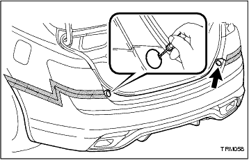
(e) Using a screwdriver, open the 2 rear bumper plates.
HINT:
Tape the screwdriver tip before use.
-
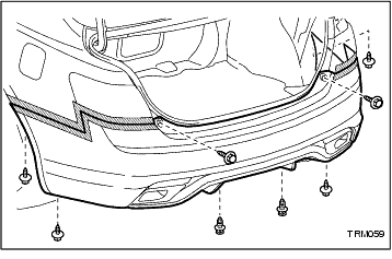
(f) Remove the 6 screws and 2 clips.
-
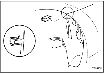
(g) Remove the clip.
HINT:
Use the same procedure for the RH side and LH side.
-
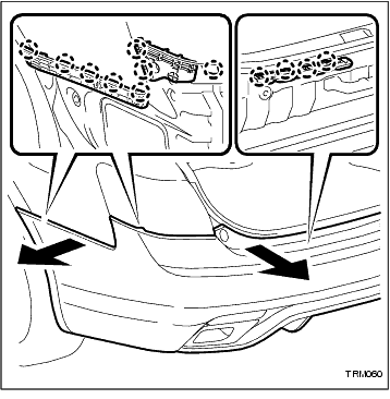
(h) Disengage the 12 claws and disconnect the rear bumper assembly as shown in the illustration.
HINT:
Use the same procedure for the RH side and LH side.
-
(i) Remove the rear bumper assembly.
-
(j) Disengage each No. 2 luggage room wire clamp from the rear bumper reinforcement sub-assembly.
-
DISASSEMBLY
1. REMOVE NO. 1 ULTRASONIC SENSOR (w/ Clearance Sonar System) (
Click Here
)
2. REMOVE NO. 1 ULTRASONIC SENSOR RETAINER (w/ Clearance Sonar System) (
Click Here
)
3. REMOVE NO. 2 ULTRASONIC SENSOR (w/ Clearance Sonar System) (
Click Here
)
4. REMOVE NO. 2 ULTRASONIC SENSOR RETAINER (w/ Clearance Sonar System) (
Click Here
)
5. REMOVE NO. 2 LUGGAGE ROOM WIRE (w/ Clearance Sonar System)
6. REMOVE REAR BUMPER BRACKET RH
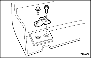
(a) Remove the 2 screws and rear bumper bracket RH.
-
7. REMOVE REAR BUMPER BRACKET LH
8. REMOVE REFLEX REFLECTOR ASSEMBLY LH
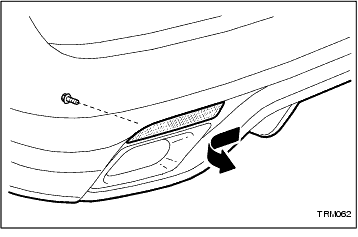
(a) Remove the screw and reflex reflector assembly LH.
-
9. REMOVE REFLEX REFLECTOR ASSEMBLY RH
10. REMOVE REAR BUMPER EXTENSION RH
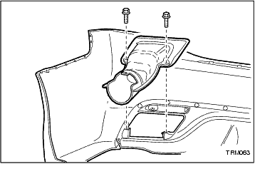
(a) Remove the 2 screws and rear bumper extension RH.
-
11. REMOVE REAR BUMPER EXTENSION LH
12. REMOVE REAR BUMPER COVER INSERT
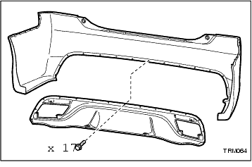
(a) Remove the 17 screws and the rear bumper cover insert.
-
13. REMOVE REAR BUMPER SIDE SUPPORT LH
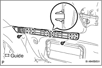
(a) Remove the 2 screws.
-
(b) Disengage the claw and 2 guides, and remove the rear bumper side support LH.
-
14. REMOVE REAR BUMPER SIDE SUPPORT RH
15. REMOVE REAR BUMPER SIDE RETAINER LH
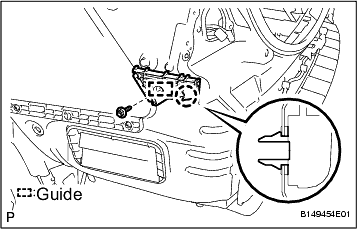
(a) Remove the screw.
-
(b) Disengage the claw and guide, and remove the rear bumper side retainer LH.
-
16. REMOVE REAR BUMPER SIDE RETAINER RH
17. REMOVE WHEEL HOUSE REINFORCEMENT LH
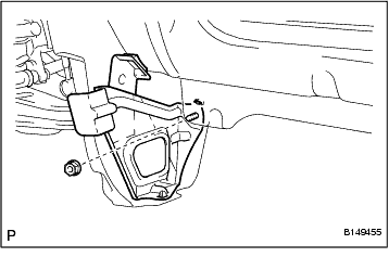
(a) Remove the nut and wheel house reinforcement LH.
-
18. REMOVE WHEEL HOUSE REINFORCEMENT RH
19. REMOVE REAR BUMPER REINFORCEMENT SUB-ASSEMBLY (for Type 1)
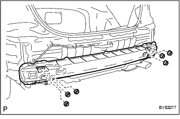
(a) Remove the 6 nuts and rear bumper reinforcement sub-assembly.
-
20. REMOVE REAR BUMPER REINFORCEMENT SUB-ASSEMBLY (for Type 2)
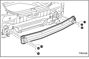
(a) Remove the 6 nuts and rear bumper reinforcement sub-assembly.
-
REASSEMBLY
NOTICE:
If a new rear bumper cover is being fitted, cut holes for the ultrasonic sensors, if fitted, before painting the new cover. Refer to the installation instructions provided with the new bumper cover.
1. INSTALL REAR BUMPER REINFORCEMENT SUB-ASSEMBLY (for Type 1)
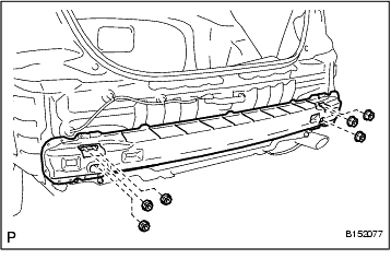
(a) Install the rear bumper reinforcement sub-assembly with the 6 nuts.
Torque:
68 N*m
(693 kgf*cm,
50 ft.*lbf)
-
2. INSTALL REAR BUMPER REINFORCEMENT SUB-ASSEMBLY (for Type 2)
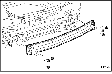
(a) Install the rear bumper reinforcement sub-assembly with the 6 nuts.
Torque:
68 N*m
(693 kgf*cm,
50 ft.*lbf)
-
3. INSTALL WHEEL HOUSE REINFORCEMENT LH
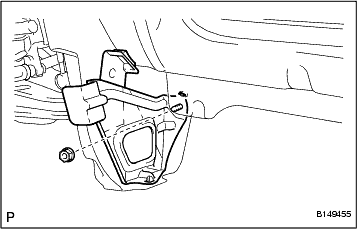
(a) Install the wheel house reinforcement LH with the nut.
-
4. INSTALL WHEEL HOUSE REINFORCEMENT RH
5. INSTALL REAR BUMPER SIDE RETAINER LH
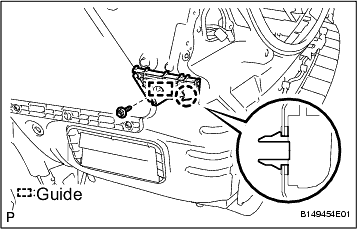
(a) Engage the claw and guide, and install the rear bumper side retainer LH.
-
(b) Install the screw.
-
6. INSTALL REAR BUMPER SIDE RETAINER RH
7. INSTALL REAR BUMPER SIDE SUPPORT LH
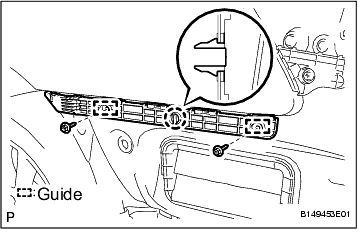
(a) Engage the claw and 2 guides, and install the rear bumper side support LH.
-
(b) Install the 2 screws.
-
8. INSTALL REAR BUMPER SIDE SUPPORT RH
9. INSTALL REAR BUMPER COVER INSERT
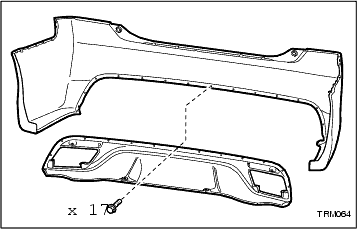
(a) Install the rear bumper cover insert with the 17 screws.
-
10. INSTALL REAR BUMPER EXTENSION RH
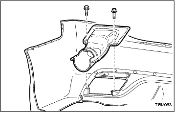
(a) Install the rear bumper extension RH with the 2 screws.
-
11. INSTALL REAR BUMPER EXTENSION LH
12. INSTALL REFLEX REFLECTOR ASSEMBLY LH
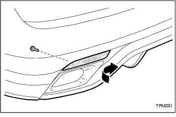
(a) Install the reflex reflector assembly LH with the screw.
-
13. INSTALL REFLEX REFLECTOR ASSEMBLY RH
14. INSTALL REAR BUMPER BRACKET RH
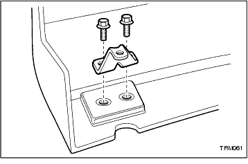
(a) Install the rear bumper bracket RH with the 2 screws.
-
15. INSTALL REAR BUMPER BRACKET LH
16. INSTALL NO. 2 LUGGAGE ROOM WIRE (w/ Clearance Sonar System)
17. INSTALL NO. 2 ULTRASONIC SENSOR RETAINER (w/ Clearance Sonar System) (
Click Here
)
18. INSTALL NO. 2 ULTRASONIC SENSOR (w/ Clearance Sonar System) (
Click Here
)
19. INSTALL NO. 1 ULTRASONIC SENSOR RETAINER (w/ Clearance Sonar System) (
Click Here
)
20. INSTALL NO. 1 ULTRASONIC SENSOR (w/ Clearance Sonar System) (
Click Here
)
INSTALLATION
1. INSTALL REAR BUMPER ASSEMBLY
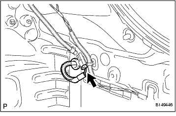
(a) Install the grommet (w/ Clearance Sonar System).
-
(b) Engage each No. 2 luggage room wire clamp to the rear bumper reinforcement sub-assembly (w/ Clearance Sonar System).
-
(c) Connect the connector (w/ Clearance Sonar System).
-
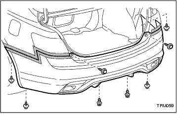
(d) Engage each claw.
-
(e) Install the rear bumper assembly with the 6 screws and 2 clips.
-
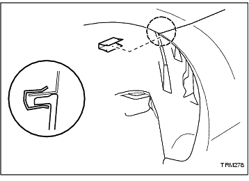
(f) Install the clip.
HINT:
Use the same procedure for the RH side and LH side.
-
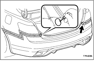
(g) Install the 2 rear bumper plates.
-
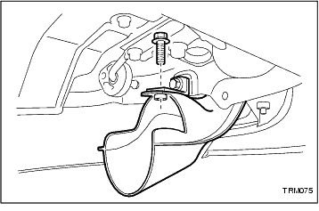
(h) Install the rear bumper extension bracket screw.
HINT:
Use the same procedure for the RH side and LH side.
-
(i) Remove the protective tape.
-
2. INSTALL LUGGAGE COMPARTMENT INNER TRIM COVER RH (w/ Clearance Sonar System) (
Click Here
)
3. INSTALL REAR FLOOR FINISH PLATE (w/ Clearance Sonar System) (
Click Here
)
4. INSTALL LUGGAGE COMPARTMENT TRIM HOOK (w/ Clearance Sonar System) (
Click Here
)
5. INSTALL SPARE WHEEL COVER ASSEMBLY (w/ Clearance Sonar System)
6. INSTALL SPARE WHEEL COVER CLAMP (w/ Clearance Sonar System)
7. INSTALL LUGGAGE COMPARTMENT FLOOR MAT (w/ Clearance Sonar System)
8. INSTALL REAR FLOOR BOARD
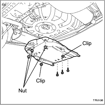
(a) Install the rear floor board with the 3 nuts, 2 clips and 3 screws.
-