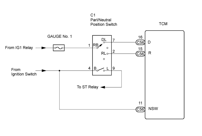
DTC P0705 Transmission Range Sensor Circuit Malfunction (PRNDL Input) |
| DTC No. | DTC Detection Condition | Trouble Area |
| P0705 | (A) Any 2 or more signals of the following are ON simultaneously (2-trip detection logic)
|
|
| READ DATA LIST |
Turn the ignition switch off.
Connect the intelligent tester together to the DLC3.
Turn the ignition switch on (IG).
Turn on the tester.
Select the item "Powertrain / ECT / Data List".
According to the display on the tester, read the "DATA LIST".
| Item | Measurement Item / Range (Display) | Normal Condition | Diagnostic Note |
| Neutral Position SW Signal | PNP SW Status / ON or OFF | Shift lever position is; P and N: ON Except P or N: OFF | When the shift lever position displayed on the intelligent tester differs from the actual position, adjustment of the PNP switch or the shift cable may be incorrect. |
| Shift SW status (R Range) | PNP SW Status / ON or OFF | Shift lever position is; R: ON Except R: OFF | When the shift lever position displayed on the intelligent tester differs from the actual position, adjustment of the PNP switch or the shift cable may be incorrect. |
| Shift SW status (D Range) | PNP SW Status / ON or OFF | Shift lever position is; D and S: ON Except D or S: OFF | When the shift lever position displayed on the intelligent tester differs from the actual position, adjustment of the PNP switch or the shift cable may be incorrect. |
| 1.CHECK HARNESS AND CONNECTOR (D, R POSITION CIRCUIT) |
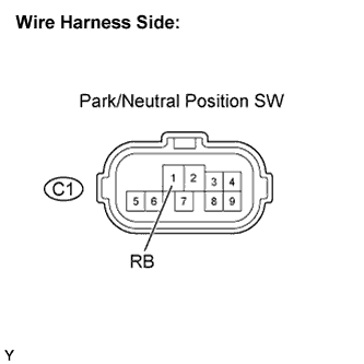 |
Disconnect the park / neutral position switch connector.
Turn the ignition switch on (IG).
Measure voltage according to the value(s) in the table below.
| Tester Connection | Specified Condition |
| RB (C1-1) - Body ground | 10 to 14 V |
|
| ||||
| OK | |
 |
| 2.CHECK HARNESS AND CONNECTOR (PARK/NEUTRAL POSITION SWITCH - ST RELAY) |
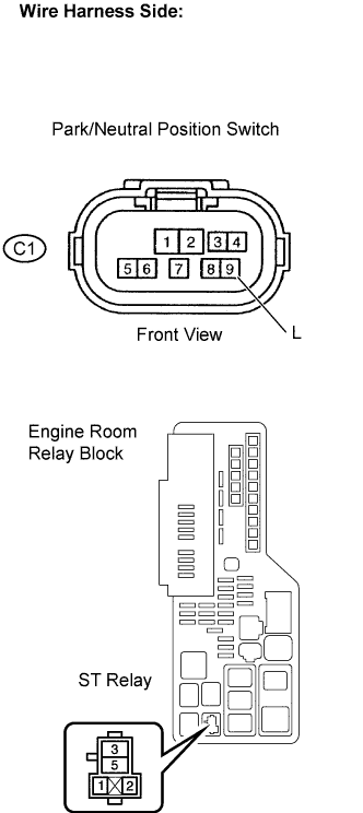 |
Disconnect the park/neutral position switch connector.
Remove the ST relay from the engine room relay block.
Measure the resistance between the terminals.
| Tester Connection | Specified Condition |
| L (C1-9) - ST relay terminal 1 | Below 1 Ω |
Install the ST relay.
Reconnect the park/neutral position switch connector.
|
| ||||
| OK | |
|
| 3.INSPECT ST RELAY |
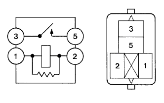 |
Remove the ST relay from the engine room relay block.
Measure the resistance between the terminals.
| Tester Connection | Specified Condition |
| 3 - 5 | 10 kΩ or higher |
| 3 - 5 | Below 1 Ω Apply battery voltage between terminals 1 and 2 |
|
| ||||
| OK | |
|
| 4.CHECK HARNESS AND CONNECTOR (ST RELAY - BODY GROUND) |
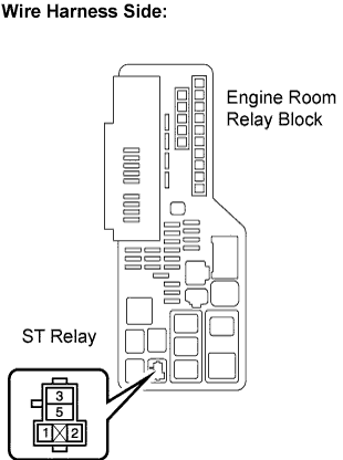 |
Remove the ST relay from the engine room relay block.
Measure the resistance between the terminals
| Tester Connection | Specified Condition |
| ST relay terminal 2 - Body ground | Below 1 Ω |
Install the ST relay.
|
| ||||
| OK | |
|
| 5.INSPECT PARK/NEUTRAL POSITION SWITCH ASSEMBLY |
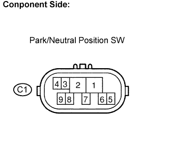 |
Measure resistance according to the value(s) in the table below when the shift lever is moved to each position.
| Shift Position | Tester Connection | Specified Condition |
| P | 1 - 3 and 4 - 9 | Below 1 Ω |
| Except P | 10 kΩ or higher | |
| R | 1 - 2 | Below 1 Ω |
| Except R | 10 kΩ or higher | |
| N | 1 - 8 and 4 - 9 | Below 1 Ω |
| Except N | 10 kΩ or higher | |
| D, S, ''+'' and ''-'' | 1 - 7 | Below 1 Ω |
| Except D, S, ''+'' and ''-'' | 10 kΩ or higher |
|
| ||||
| OK | |
|
| 6.CHECK HARNESS AND CONNECTOR |
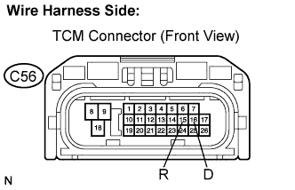 |
Connect the park/neutral position switch connector.
Disconnect the TCM connectors.
Turn the ignition switch to the ON position, and measure the voltage according to the value(s) in the table below when the shift lever is moved to each position.
| Shift Position | Tester Connection | Specified Condition |
| R | R (C56-15) - Body ground | 10 to 14 V * |
| Except R | Below 1 V | |
| D | D (C56-16) - Body ground | 10 to 14 V |
| Except D | Below 1 V |
|
| ||||
| OK | |
|
| 7.CHECK HARNESS AND CONNECTOR (PARK/NEUTRAL POSITION SWITCH - ECM) |
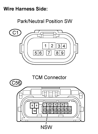 |
Disconnect the ECM connectors.
Turn the ignition switch off.
Measure resistance according to the value(s) in the table below.
| Tester Connection | Specified Condition |
| B (C1-4) - NSW (C56-11) | Below 1 Ω |
| Tester Connection | Specified Condition |
| B (C1-4) or NSW (C56-11) - Body ground | 10 kΩ or higher |
|
| ||||
| OK | ||
 | ||
| ||
