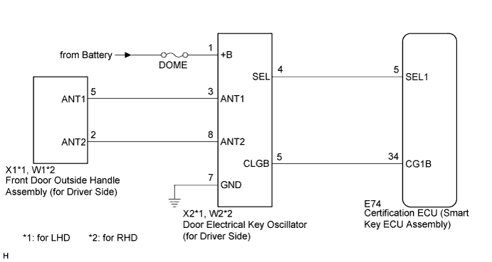
ENTRY AND START SYSTEM > Driver Side Door Entry Lock and Unlock Functions do not Operate |
| 1.CHECK POWER DOOR LOCK OPERATION |
When the door control switch on the master switch assembly is operated, check that the locked doors unlock (Click here).
|
| ||||
| OK | |
 |
| 2.READ VALUE USING INTELLIGENT TESTER (DOOR OUTSIDE HANDLE) |
Connect the intelligent tester to the DLC3.
Turn the engine switch on (IG).
Turn the intelligent tester on.
Enter the following menus: Body / Entry & Start / Data List.
Read the Data List according to the display on the intelligent tester.
| Tester Display | Measurement Item/Range | Normal Condition | Diagnostic Note |
| D-Door Touch Sensor | Driver side door touch sensor / ON or OFF | ON: Touch sensor is touched OFF: Touch sensor is not touched | - |
| D-Door Trigger SW | Driver side door lock switch / ON or OFF | ON: Entry lock switch is pressed OFF: Entry lock switch is not pressed | - |
|
| ||||
| OK | |
|
| 3.CHECK WAVE ENVIRONMENT |
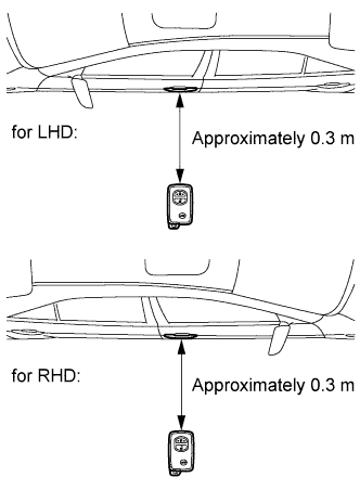 |
Bring the electrical key transmitter near the front door outside handle assembly (for driver side), and perform a driver door entry lock and unlock operation check.
|
| ||||
| OK | ||
 | ||
| ||
| 4.PERFORM KEY DIAGNOSTIC MODE INSPECTION |
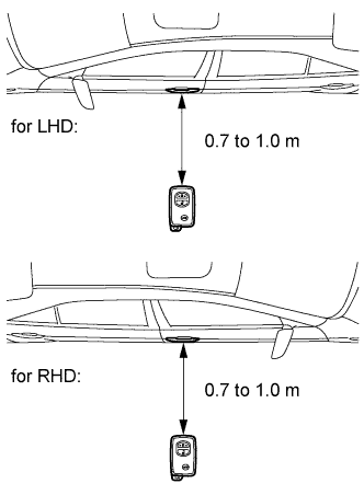 |
Diagnostic mode inspection (door electrical key oscillator (for driver side))
Connect the intelligent tester to the DLC3.
Turn the engine switch on (IG).
Turn the intelligent tester on.
Enter the following menus: Body / Entry & Start / Utility / Key Communication Check / Overhead + Driver Side.
When the electrical key transmitter is in the position shown in the illustration, check that the wireless door lock buzzer sounds.
|
| ||||
| OK | ||
| ||
| ||
| 5.CHECK HARNESS AND CONNECTOR (CERTIFICATION ECU - DOOR ELECTRICAL KEY OSCILLATOR) |
Disconnect the certification ECU (smart key ECU assembly) connector.
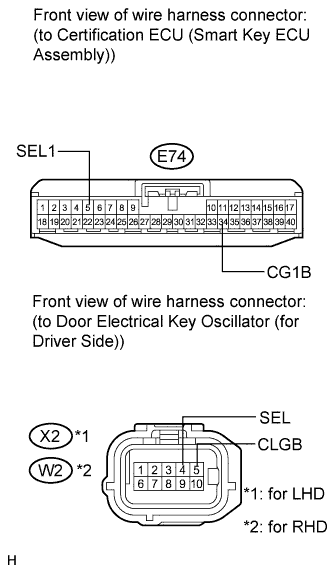 |
Disconnect the door electrical key oscillator (for driver side) connector.
Measure the resistance according to the value(s) in the table below.
| Tester Connection | Condition | Specified Condition |
| E74-5 (SEL1) - X2-4 (SEL) | Always | Below 1 Ω |
| E74-34 (CG1B) - X2-5 (CLGB) | Always | Below 1 Ω |
| E74-5 (SEL1) - Body ground | Always | 10 kΩ or higher |
| E74-34 (CG1B) - Body ground | Always | 10 kΩ or higher |
| Tester Connection | Condition | Specified Condition |
| E74-5 (SEL1) - W2-4 (SEL) | Always | Below 1 Ω |
| E74-34 (CG1B) - W2-5 (CLGB) | Always | Below 1 Ω |
| E74-5 (SEL1) - Body ground | Always | 10 kΩ or higher |
| E74-34 (CG1B) - Body ground | Always | 10 kΩ or higher |
|
| ||||
| OK | |
|
| 6.CHECK HARNESS AND CONNECTOR (DOOR ELECTRICAL KEY OSCILLATOR - FRONT DOOR OUTSIDE HANDLE) |
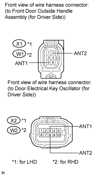 |
Disconnect the front door outside handle assembly (for driver side) connector.
Measure the resistance according to the value(s) in the table below.
| Tester Connection | Condition | Specified Condition |
| X1-2 (ANT2) - X2-8 (ANT2) | Always | Below 1 Ω |
| X1-5 (ANT1) - X2-3 (ANT1) | Always | Below 1 Ω |
| X1-2 (ANT2) - Body ground | Always | 10 kΩ or higher |
| X1-5 (ANT1) - Body ground | Always | 10 kΩ or higher |
| Tester Connection | Condition | Specified Condition |
| W1-2 (ANT2) - W2-8 (ANT2) | Always | Below 1 Ω |
| W1-5 (ANT1) - W2-3 (ANT1) | Always | Below 1 Ω |
| W1-2 (ANT2) - Body ground | Always | 10 kΩ or higher |
| W1-5 (ANT1) - Body ground | Always | 10 kΩ or higher |
|
| ||||
| OK | |
|
| 7.INSPECT FUSE (DOME) |
Remove the DOME fuse from the instrument panel junction block assembly.
Measure the resistance according to the value(s) in the table below.
| Tester Connection | Condition | Specified Condition |
| DOME fuse | Always | Below 1 Ω |
|
| ||||
| OK | |
|
| Go to step 9 |
| 8.CHECK HARNESS AND CONNECTOR (DOOR ELECTRICAL KEY OSCILLATOR - BATTERY AND BODY GROUND) |
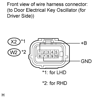 |
Measure the voltage according to the value(s) in the table below.
| Tester Connection | Condition | Specified Condition |
| X2-1 (+B) - X2-7 (GND) | Always | 11 to 14 V |
| Tester Connection | Condition | Specified Condition |
| W2-1 (+B) - W2-7 (GND) | Always | 11 to 14 V |
|
| ||||
| OK | |
|
| 9.REPLACE DOOR ELECTRICAL KEY OSCILLATOR (for Driver Side) |
Replace the door electrical key oscillator (for driver side) (Click here).
| NEXT | |
|
| 10.CHECK DOOR ELECTRICAL KEY OSCILLATOR (for Driver Side) |
Check that the entry functions operate normally (Click here).
|
| ||||
| OK | ||
| ||
| ||

