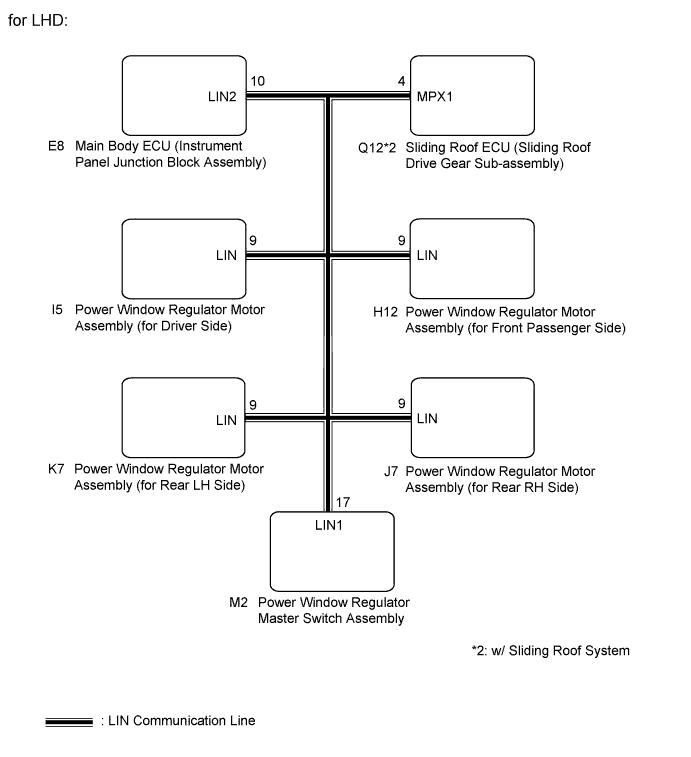
DTC B2325 LIN Communication Bus Malfunction |
| DTC Code | DTC Detection Condition | Trouble Area |
| B2325 | Main body ECU (instrument panel junction block) detects errors in communication with the ECUs connected to the door bus lines 3 times in a row. |
|
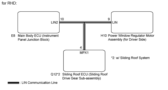
| 1.SYSTEM CHECK |
Check the vehicle specification.
| Result | Proceed to |
| for LHD | A |
| for RHD | B |
|
| ||||
| A | |
 |
| 2.CHECK HARNESS AND CONNECTOR (MAIN BODY ECU - EACH ECU) |
Disconnect the E8 and Q12*2 ECU connectors.
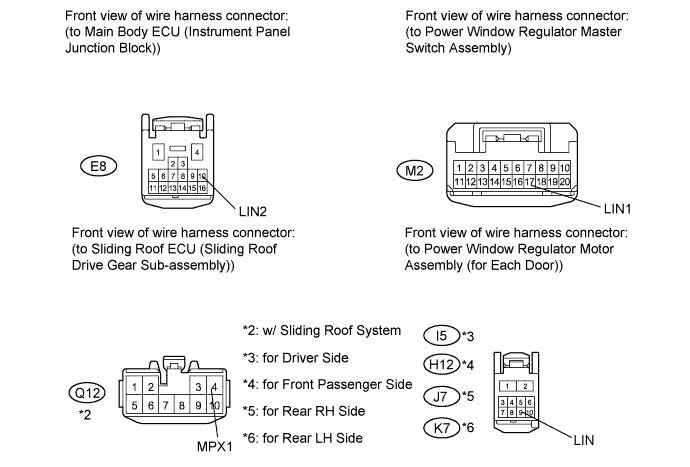
Disconnect the I5, H12, J7 and K7 motor connectors.
Disconnect the M2 switch connector.
Measure the resistance and voltage according to the value(s) in the table below.
| Tester Connection | Condition | Specified Condition |
| E8-10 (LIN2) - M2-17 (LIN1) | Always | Below 1 Ω |
| E8-10 (LIN2) - I5-9 (LIN) | Always | Below 1 Ω |
| E8-10 (LIN2) - H12-9 (LIN) | Always | Below 1 Ω |
| E8-10 (LIN2) - J7-9 (LIN) | Always | Below 1 Ω |
| E8-10 (LIN2) - K7-9 (LIN) | Always | Below 1 Ω |
| E8-10 (LIN2) - Q12-4 (MPX1)*2 | Always | Below 1 Ω |
| E8-10 (LIN2) - Body ground | Always | 10 kΩ or higher |
| Tester Connection | Condition | Specified Condition |
| E8-10 (LIN2) - Body ground | Always | Below 1 V |
|
| ||||
| OK | |
|
| 3.CHECK DTC OUTPUT (POWER WINDOW REGULATOR MOTOR ASSEMBLY (for DRIVER SIDE)) |
Reconnect the E8 and Q12*2 ECU connectors.
Reconnect the H12, J7 and K7 motor connectors.
Reconnect the M2 switch connector.
Clear the DTC (Click here).
Recheck for DTCs.
| Result | Proceed to |
| DTC B2325 is output | A |
| DTC B2325 is not output | B |
|
| ||||
| A | |
|
| 4.CHECK DTC OUTPUT (POWER WINDOW REGULATOR MOTOR ASSEMBLY (for FRONT PASSENGER SIDE)) |
Reconnect the I5 motor connector.
Disconnect the H12 motor connector.
Clear the DTC (Click here).
Recheck for DTCs.
| Result | Proceed to |
| DTC B2325 is output | A |
| DTC B2325 is not output | B |
|
| ||||
| A | |
|
| 5.CHECK DTC OUTPUT (POWER WINDOW REGULATOR MOTOR ASSEMBLY (for REAR RH SIDE)) |
Reconnect the H12 motor connector.
Disconnect the J7 motor connector.
Clear the DTC (Click here).
Recheck for DTCs.
| Result | Proceed to |
| DTC B2325 is output | A |
| DTC B2325 is not output | B |
|
| ||||
| A | |
|
| 6.CHECK DTC OUTPUT (POWER WINDOW REGULATOR MOTOR ASSEMBLY (for REAR LH SIDE)) |
Reconnect the J7 motor connector.
Disconnect the K7 motor connector.
Clear the DTC (Click here).
Recheck for DTCs.
| Result | Proceed to |
| DTC B2325 is output | A |
| DTC B2325 is not output | B |
|
| ||||
| A | |
|
| 7.CHECK DTC OUTPUT (POWER WINDOW REGULATOR MASTER SWITCH ASSEMBLY) |
Reconnect the K7 motor connector.
Disconnect the M2 switch connector.
Clear the DTC (Click here).
Recheck for DTCs.
| Result | Proceed to |
| DTC B2325 is output (w/ Sliding Roof System) | A |
| DTC B2325 is output (w/o Sliding Roof System) | B |
| DTC B2325 is not output | C |
|
| ||||
|
| ||||
| A | |
|
| 8.CHECK DTC OUTPUT (SLIDING ROOF ECU (SLIDING ROOF DRIVE GEAR SUB-ASSEMBLY)) |
Reconnect the M2 switch connector.
Disconnect the Q12 ECU connector.
Clear the DTC (Click here).
Recheck for DTCs.
| Result | Proceed to |
| DTC B2325 is output | A |
| DTC B2325 is not output | B |
|
| ||||
| A | ||
 | ||
| ||
| 9.CHECK HARNESS AND CONNECTOR (MAIN BODY ECU - EACH ECU) |
Disconnect the E8 and H10 connectors.
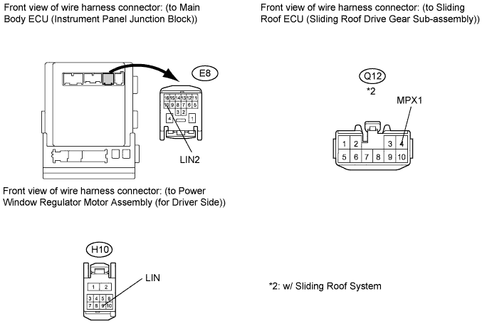
Disconnect the Q12*2 connector.
Measure the resistance and voltage according to the value(s) in the table below.
| Tester Connection | Condition | Specified Condition |
| E8-10 (LIN2) - H10-9 (LIN) | Always | Below 1 Ω |
| E8-10 (LIN2) - Q12-4 (MPX1)*2 | Always | Below 1 Ω |
| E8-10 (LIN2) - Body ground | Always | 10 kΩ or higher |
| Tester Connection | Condition | Specified Condition |
| E8-10 (LIN2) - Body ground | Always | Below 1 V |
|
| ||||
| OK | |
|
| 10.CHECK DTC OUTPUT (POWER WINDOW REGULATOR MOTOR ASSEMBLY (FOR DRIVER SIDE)) |
Reconnect the E8 and Q12*2 connectors.
Clear the DTC (Click here).
Recheck for DTCs.
| Result | Proceed to |
| B2325 is output (w/ Sliding Roof System) | A |
| B2325 is output (w/o Sliding Roof System) | B |
| B2325 is not output | C |
|
| ||||
|
| ||||
| A | |
|
| 11.CHECK DTC OUTPUT (SLIDING ROOF ECU (SLIDING ROOF DRIVE GEAR SUB-ASSEMBLY)) |
Reconnect the H10 connector.
Disconnect the Q12 connector.
Clear the DTC (Click here).
Recheck for DTCs.
| Result | Proceed to |
| B2325 is output | A |
| B2325 is not output | B |
|
| ||||
| A | ||
| ||
| ||

