FRONT SUSPENSION FRONT LOWER SUSPENSION ARM(for Manual Transaxle) REMOVAL
PROCEDURE

 1. PRECAUTION
- NOTICE:
-
After turning the ignition switch off, waiting time may be required before disconnecting the cable from the negative (-) battery terminal. Therefore, make sure to read the disconnecting the cable from the negative (-) battery terminal notices before proceeding with work.
-
Click hereGeneral>INTRODUCTION>REPAIR INSTRUCTION>PRECAUTION
2.DISCONNECT CABLE FROM NEGATIVE BATTERY TERMINAL
- NOTICE:
-
When disconnecting the cable, some systems need to be initialized after the cable is reconnected.
-
Click hereGeneral>INTRODUCTION>REPAIR INSTRUCTION>INITIALIZATION
3.REMOVE FRONT WHEELS
4.REMOVE WINDSHIELD WIPER MOTOR AND LINK ASSEMBLY
55702A
5.REMOVE FRONT OUTER COWL TOP PANEL SUB-ASSEMBLY
6.REMOVE AIR CLEANER CAP SUB-ASSEMBLY
17801
7.REMOVE AIR CLEANER FILTER ELEMENT SUB-ASSEMBLY
8.REMOVE AIR CLEANER CASE SUB-ASSEMBLY
51442C
9.REMOVE ENGINE UNDER COVER LH
51441C
10.REMOVE ENGINE UNDER COVER RH
53737B
11.REMOVE FRONT FENDER APRON SEAL LH (for LH Side)
53736
12.REMOVE FRONT FENDER APRON SEAL RH (for RH Side)
12361A
13.SEPARATE FRONT ENGINE MOUNTING INSULATOR
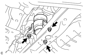
Remove the 3 nuts to separate the front engine mounting insulator from the front frame assembly.
12364A
14.SEPARATE ENGINE LATERAL CONTROL ROD
Remove the 2 hole plugs.
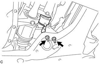
Remove the 2 nuts to separate the engine lateral control rod from the front frame assembly.
12372A
15.REMOVE ENGINE MOUNTING INSULATOR LH (for LH Side)
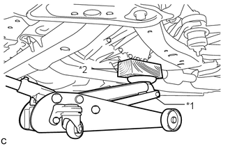
| *1 | Jack |
| *2 | Wooden Block |
Using a jack and a wooden block, support the engine assembly with transaxle at the position shown in the illustration.
- NOTICE:
- ·
Do not position the wooden block on the oil pan.
·Do not damage the components surrounding the engine assembly with transaxle.
·Ensure that the jack and wooden block are stable.
·Keep the engine assembly with transaxle supported until installation of the engine mounting insulator LH is complete.
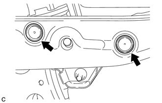
Remove the 2 hole plugs.
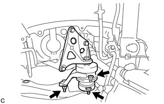
Remove the 3 nuts from the engine mounting insulator LH.
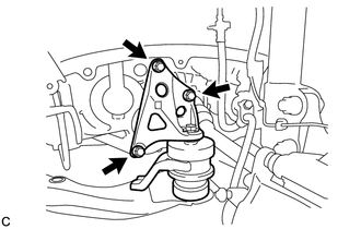
Remove the 3 bolts and separate the engine mounting insulator LH from the manual transaxle assembly.
While ensuring that there is no interference from the components surrounding the engine, tilt the engine assembly with transaxle to a position that allows the engine mounting insulator LH to be removed.
- NOTICE:
-
Tilt the engine assembly with transaxle as little as possible.
Remove the engine mounting insulator LH from the front frame assembly.
48069
16.REMOVE FRONT LOWER NO. 1 SUSPENSION ARM SUB-ASSEMBLY LH (for LH Side)
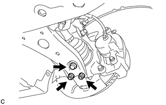
Remove the bolt and 2 nuts, and separate the front lower No. 1 suspension arm sub-assembly LH from the front lower ball joint assembly.
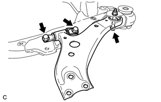
Remove the 3 bolts, nut and front lower No. 1 suspension arm sub-assembly LH from the front frame assembly.
- NOTICE:
-
When removing the bolt, keep the nut from rotating.
Remove the front lower arm bushing stopper from the front lower No. 1 suspension arm sub-assembly LH.
82284
17.SEPARATE EARTH WIRE (for RH Side)
12327A
18.REMOVE NO. 2 ENGINE MOUNTING STAY RH (for RH Side)
12309
19.REMOVE ENGINE MOVING CONTROL ROD SUB-ASSEMBLY (for RH Side)
12362A
20.REMOVE ENGINE MOUNTING INSULATOR RH (for RH Side)
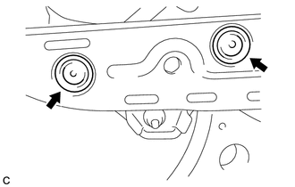
Remove the 2 hole plugs.
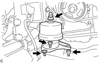
Remove the 4 nuts from the engine mounting insulator RH.
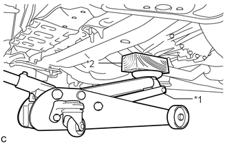
| *1 | Jack |
| *2 | Wooden Block |
Using a jack and a wooden block, support the engine assembly with transaxle at the position shown in the illustration. While ensuring that there is no interference from the components surrounding the engine, tilt the engine assembly with transaxle to a position that allows the engine mounting insulator RH to be removed.
- NOTICE:
- ·
Do not position the wooden block on the oil pan.
·Do not damage the components surrounding the engine assembly with transaxle.
·Tilt the engine assembly with transaxle as little as possible.
·Ensure that the jack and wooden block are stable.
·Keep the engine assembly with transaxle supported until installation of the engine mounting insulator RH is complete.
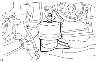
Remove the engine mounting insulator RH from the front frame assembly.
48068
21.REMOVE FRONT LOWER NO. 1 SUSPENSION ARM SUB-ASSEMBLY RH (for RH Side)
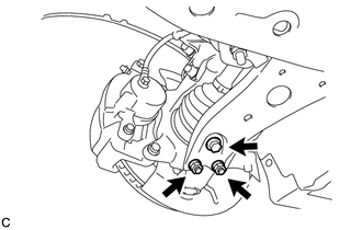
Remove the bolt and 2 nuts, and separate the front lower No. 1 suspension arm sub-assembly RH from the front lower ball joint assembly.
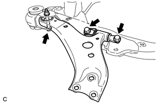
Remove the 3 bolts, nut and front lower No. 1 suspension arm sub-assembly RH from the front frame assembly.
- NOTICE:
-
When removing the bolt, keep the nut from rotating.
Remove the front lower arm bushing stopper from the front lower No. 1 suspension arm sub-assembly RH.