BRAKE SYSTEM (OTHER) BRAKE BOOSTER(for RHD) INSTALLATION
PROCEDURE

 44696
1.INSTALL CHECK VALVE GROMMET
Install a new check valve grommet to the brake booster assembly.
44730
2.INSTALL BRAKE VACUUM CHECK VALVE ASSEMBLY
Install the brake vacuum check valve assembly to the brake booster assembly.
47264D
3.INSTALL BRAKE MASTER CYLINDER PUSH ROD CLEVIS
Temporarily install the lock nut and brake master cylinder push rod clevis to the brake booster assembly.
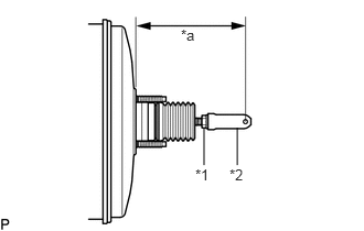
| *1 | Lock Nut |
| *2 | Brake Master Cylinder Push Rod Clevis |
| *a | Push Rod Length |
Set the push rod length as shown in the illustration.
- Push rod length:
148.6 to 149.6 mm (5.86 to 5.88 in.)
Tighten the lock nut.
- Torque:
- 26 N*m (265 kgf*cm, 19 ft.*lbf)
44785
4.INSTALL BRAKE BOOSTER GASKET
Install a new brake booster gasket to the brake booster assembly.
44610
5.INSTALL BRAKE BOOSTER ASSEMBLY
Install the brake booster assembly to the vehicle body with the 4 nuts.
- Torque:
- 13 N*m (131 kgf*cm, 9 ft.*lbf)
- NOTICE:
-
Do not kink or damage the brake lines, air conditioning tube and accessory assembly or suction hose sub-assembly.
47264A
6.INSTALL PUSH ROD PIN
44773F
7.CONNECT UNION TO CHECK VALVE HOSE
Connect the union to check valve hose to the brake booster assembly, and slide the clip to secure it.
17650
8.INSTALL VACUUM SWITCHING VALVE ASSEMBLY
Install the vacuum switching valve assembly with the bolt.
- Torque:
- 9.0 N*m (92 kgf*cm, 80 in.*lbf)
Connect the 2 vacuum hoses and connector.
Connect the union to check valve hose and wire harness clamp.
9.CONNECT BRAKE LINE
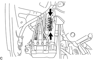
Install 2 new clamps to the brake lines.
Using a union nut wrench, connect the 2 brake lines to the brake actuator assembly.
- Torque:
- 20 N*m (199 kgf*cm, 14 ft.*lbf)
- NOTICE:
- ·
Do not kink or damage the brake lines.
·Do not allow any foreign matter such as dirt and dust to enter the brake lines.
·Use the formula to calculate special torque values for situations where the union nut wrench is combined with a torque wrench.
Click hereGeneral>INTRODUCTION>REPAIR INSTRUCTION>PRECAUTION
47371A
10.INSTALL NO. 1 BRAKE TUBE CLAMP
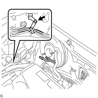
Install a new No. 1 brake tube clamp to the vehicle body.
- Torque:
- 7.8 N*m (80 kgf*cm, 69 in.*lbf)
Engage the brake lines to the clamp.
- NOTICE:
-
Do not kink or damage the brake lines.
88704
11.INSTALL SUCTION HOSE SUB-ASSEMBLY
Remove the attached vinyl tape from the openings of the disconnected parts.
Sufficiently apply compressor oil to a new O-ring, fitting surface of the suction hose sub-assembly and air conditioning unit.
- Compressor oil:
ND-OIL 8 or equivalent
Install the O-ring on the suction hose sub-assembly.
- NOTICE:
-
Keep the O-ring and O-ring fitting surfaces free from dirt or any foreign matter.
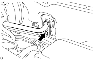
Insert the suction hose sub-assembly to the air conditioning unit.
- NOTICE:
- ·
Insert the pipe joint into the fitting hole securely.
·Do not deform the piping.
·Do not damage the clamp.
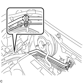
Install the clamp with suction hose sub-assembly and air conditioning tube and accessory assembly to the No. 1 brake tube clamp.
- NOTICE:
- ·
Do not deform the air conditioning tube and accessory assembly or suction hose sub-assembly.
·Do not damage the clamp.
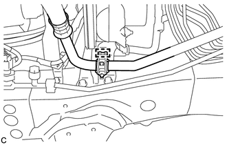
Install the clamp to the brake actuator bracket assembly.
- NOTICE:
- ·
Do not deform the suction hose sub-assembly.
·Do not damage the clamp.
88710E
12.INSTALL AIR CONDITIONING TUBE AND ACCESSORY ASSEMBLY
Remove the attached vinyl tape from the openings of the disconnected parts.
Sufficiently apply compressor oil to 2 new O-rings, the fitting surface of the air conditioning tube and accessory assembly, cooler condenser assembly and air conditioning unit.
- Compressor oil:
ND-OIL 8 or equivalent
Install the 2 O-rings on the air conditioning tube and accessory assembly.
- NOTICE:
-
Keep the O-ring and O-ring fitting surfaces free from dirt or any foreign matter.
Insert the air conditioning tube and accessory assembly to the cooler condenser assembly.
Install the bolt.
- Torque:
- 9.8 N*m (100 kgf*cm, 87 in.*lbf)
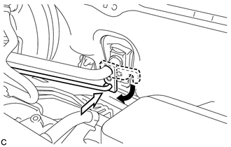
Insert the air conditioning tube and accessory assembly to the air conditioning unit.
- NOTICE:
-
Insert the pipe joint into the fitting hole securely.
Turn the hook connector and install the bolt.
- Torque:
- 9.8 N*m (100 kgf*cm, 87 in.*lbf)
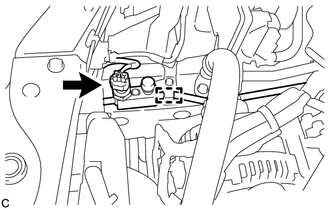
Install the clamp to the vehicle body and connect the pressure sensor connector.
- NOTICE:
- ·
Do not deform the piping.
·Do not damage the clamp.
53293C
13.INSTALL RADIATOR SIDE DEFLECTOR RH
47201
14.INSTALL BRAKE MASTER CYLINDER SUB-ASSEMBLY
15.CONNECT CABLE TO NEGATIVE BATTERY TERMINAL
- NOTICE:
-
When disconnecting the cable, some systems need to be initialized after the cable is reconnected.
-
Click hereGeneral>INTRODUCTION>REPAIR INSTRUCTION>INITIALIZATION
16. CHARGE AIR CONDITIONING SYSTEM WITH REFRIGERANT
17. WARM UP ENGINE
18.INSPECT FOR REFRIGERANT LEAK
52119A
19.INSTALL FRONT BUMPER COVER
20.INSPECT AND ADJUST BRAKE PEDAL