Home › Audio / Visual / Telematics › AUDIO / VIDEO › AUDIO AND VISUAL SYSTEM(for Radio and Display Type) › 2011.10–2015.04
RM19V0EQ _56 Audio / Visual / Telematics _014599 AUDIO / VIDEO _0074081 AUDIO AND VISUAL SYSTEM(for Radio and Display Type) C

AUDIO / VIDEO  AUDIO AND VISUAL SYSTEM(for Radio and Display Type)  B15C3  Speaker Output Short  


DESCRIPTION

This DTC is stored when a malfunction occurs in the speakers.

DTC No. Detection Item DTC Detection Condition Trouble Area
B15C3 Speaker Output Short A short is detected in the speaker output circuit.
·

Harness or connector

·

Speaker

·

Radio and display receiver assembly


WIRING DIAGRAM

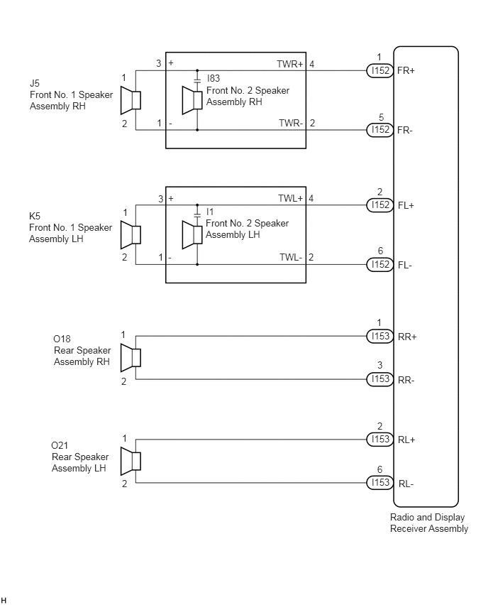
E226481E27
5.729,7.5 6.958,8.104 1.229,0.604 10 false Radio and Display Receiver Assembly 3.031,1.24 4.313,1.896 1.281,0.656 10 false Front No. 2 Speaker Assembly RH 5.531,0.75 5.635,0.906 0.104,0.156 10 false 1 4.542,0.854 4.646,1.01 0.104,0.156 10 false 4 4.552,1.719 4.656,1.875 0.104,0.156 10 false 2 2.292,0.844 2.396,1 0.104,0.156 10 false 3 2.302,1.719 2.406,1.875 0.104,0.156 10 false 1 2.469,0.833 2.573,0.99 0.104,0.156 10 false + 2.479,1.719 2.583,1.875 0.104,0.156 10 false - 4.094,1.719 4.531,1.875 0.438,0.156 10 false TWR- 4.083,2.823 4.521,2.979 0.438,0.156 10 false TWL+ 4.104,3.688 4.542,3.844 0.438,0.156 10 false TWL- 4.063,0.854 4.5,1.01 0.438,0.156 10 false TWR+ 5.458,0.948 5.76,1.104 0.302,0.156 10 false I152 3.042,1.063 3.302,1.219 0.26,0.156 10 false I83 0.438,1.302 1.719,1.958 1.281,0.656 10 false Front No. 1 Speaker Assembly RH 0.438,1.135 0.698,1.292 0.26,0.156 10 false J5 3.021,3.188 4.302,3.844 1.281,0.656 10 false Front No. 2 Speaker Assembly LH 4.531,2.823 4.635,2.979 0.104,0.156 10 false 4 4.531,3.688 4.635,3.844 0.104,0.156 10 false 2 2.323,2.833 2.427,2.99 0.104,0.156 10 false 3 2.323,3.688 2.427,3.844 0.104,0.156 10 false 1 2.469,2.823 2.573,2.979 0.104,0.156 10 false + 2.469,3.688 2.573,3.844 0.104,0.156 10 false - 3.031,3.021 3.292,3.177 0.26,0.156 10 false I1 0.427,3.25 1.708,3.906 1.281,0.656 10 false Front No. 1 Speaker Assembly LH 0.427,3.083 0.688,3.24 0.26,0.156 10 false K5 0.792,5.052 1.698,5.708 0.906,0.656 10 false Rear Speaker Assembly RH 0.781,4.885 1.094,5.042 0.313,0.156 10 false O18 0.76,6.615 1.667,7.271 0.906,0.656 10 false Rear Speaker Assembly LH 0.75,6.448 1.042,6.604 0.292,0.156 10 false O21 5.458,1.813 5.76,1.969 0.302,0.156 10 false I152 5.458,2.917 5.76,3.073 0.302,0.156 10 false I152 5.458,3.792 5.76,3.948 0.302,0.156 10 false I152 5.458,4.844 5.76,5 0.302,0.156 10 false I153 5.458,5.469 5.76,5.625 0.302,0.156 10 false I153 5.458,6.354 5.76,6.51 0.302,0.156 10 false I153 5.458,6.99 5.75,7.146 0.292,0.156 10 false I153 5.833,0.948 6.125,1.104 0.292,0.156 10 false FR+ 5.833,1.823 6.094,1.979 0.26,0.156 10 false FR- 5.844,2.927 6.25,3.146 0.406,0.219 10 false FL+ 5.844,3.802 6.104,3.958 0.26,0.156 10 false FL- 5.844,4.854 6.146,5.01 0.302,0.156 10 false RR+ 5.844,5.49 6.125,5.646 0.281,0.156 10 false RR- 5.844,6.365 6.125,6.521 0.281,0.156 10 false RL+ 5.854,7.01 6.115,7.167 0.26,0.156 10 false RL- 5.542,6.802 5.646,6.958 0.104,0.156 10 false 6 5.542,6.167 5.646,6.323 0.104,0.156 10 false 2 5.542,5.271 5.646,5.427 0.104,0.156 10 false 3 5.531,4.646 5.635,4.802 0.104,0.156 10 false 1 5.552,3.594 5.656,3.75 0.104,0.156 10 false 6 5.542,2.729 5.729,2.927 0.188,0.198 10 false 2 5.563,1.635 5.667,1.792 0.104,0.156 10 false 5 1.781,1.052 1.885,1.208 0.104,0.156 10 false 1 1.792,1.729 1.896,1.885 0.104,0.156 10 false 2 1.802,3.031 1.906,3.188 0.104,0.156 10 false 1 1.792,3.688 1.896,3.844 0.104,0.156 10 false 2 1.771,4.823 1.875,4.979 0.104,0.156 10 false 1 1.781,5.51 1.885,5.667 0.104,0.156 10 false 2 1.792,6.344 1.896,6.5 0.104,0.156 10 false 1 1.792,7.01 1.896,7.167 0.104,0.156 10 false 2


PROCEDURE

1.CHECK HARNESS AND CONNECTOR
a.

Disconnect the connectors from the radio and display receiver assembly and speakers.


b.

Measure the resistance between the radio and display receiver assembly and body ground to check for a short circuit in the wire harness.

Standard Resistance:
Tester Connection Condition Specified Condition
I152-1 (FR+) - Body ground Always 10 kΩ or higher
I152-5 (FR-) - Body ground Always 10 kΩ or higher
I152-2 (FL+) - Body ground Always 10 kΩ or higher
I152-6 (FL-) - Body ground Always 10 kΩ or higher
I153-1 (RR+) - Body ground Always 10 kΩ or higher
I153-3 (RR-) - Body ground Always 10 kΩ or higher
I153-2 (RL+) - Body ground Always 10 kΩ or higher
I153-6 (RL-) - Body ground Always 10 kΩ or higher


c.

Measure the resistance between each of the front No. 2 speaker assemblies and body ground to check for a short circuit in the wire harness.

Standard Resistance:
Tester Connection Condition Specified Condition
I83-3 (+) - Body ground Always 10 kΩ or higher
I83-1 (-) - Body ground Always 10 kΩ or higher
I1-3 (+) - Body ground Always 10 kΩ or higher
I1-1 (-) - Body ground Always 10 kΩ or higher


Result:
Proceed to
OK
NG


OK

2.INSPECT FRONT NO. 1 SPEAKER ASSEMBLY

NG

REPAIR OR REPLACE HARNESS OR CONNECTOR

2.INSPECT FRONT NO. 1 SPEAKER ASSEMBLY
a.

Resistance check

i.
E219303C52
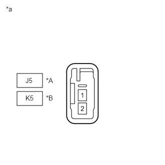
0.354,1.906 0.885,2.198 0.531,0.292 0.354,1.531 0.885,1.823 0.531,0.292 0.531,1.958 0.938,2.24 0.406,0.281 10 false K5 0.531,1.594 0.948,1.865 0.417,0.271 10 false J5 0.125,0.104 0.469,0.438 0.344,0.333 10 false *a 0.958,1.594 1.365,1.958 0.406,0.365 10 false *A 0.958,1.958 1.333,2.281 0.375,0.323 10 false *B
*A for RH
*B for LH
*a Component without harness connected
(Front No. 1 Speaker Assembly)


Measure the resistance according to the value(s) in the table below.

Standard Resistance:
Tester Connection Condition Specified Condition
J5-1 - J5-2 Always 3.2 to 4.8 Ω
K5-1 - K5-2 Always 3.2 to 4.8 Ω


Result:
Proceed to
OK
NG


OK

3.INSPECT FRONT NO. 2 SPEAKER ASSEMBLY

NG

REPLACE FRONT NO. 1 SPEAKER ASSEMBLY

3.INSPECT FRONT NO. 2 SPEAKER ASSEMBLY
a.

Resistance check

i.
E226097C23
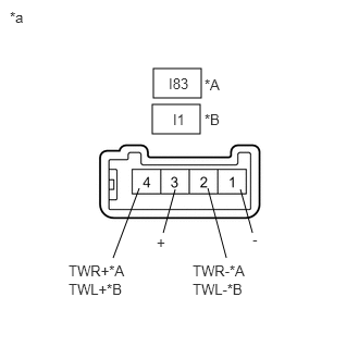
1.469,0.656 1.927,0.938 0.458,0.281 1.458,1 1.917,1.281 0.458,0.281 1.333,1.802 1.083,2.469 false 1.677,1.813 1.563,2.229 false 2.302,1.813 2.417,2.229 false 1.99,1.802 2.167,2.469 false 0.094,0.083 0.479,0.385 0.385,0.302 10 false *a 1.958,0.729 2.531,1.083 0.573,0.354 10 false *A 1.958,1.063 2.396,1.365 0.438,0.302 10 false *B 1.615,0.719 2.094,1 0.479,0.281 10 false I83 1.656,1.063 2.135,1.396 0.479,0.333 10 false I1 1.5,2.24 1.844,2.594 0.344,0.354 10 false + 0.656,2.51 1.5,2.813 0.844,0.302 10 false TWR+*A 0.656,2.688 1.51,3.021 0.854,0.333 10 false TWL+*B 1.844,2.51 2.583,2.719 0.74,0.208 10 false TWR-*A 1.844,2.688 2.583,2.958 0.74,0.271 10 false TWL-*B 2.417,2.208 2.708,2.563 0.292,0.354 10 false -
*A for RH
*B for LH
*a Component without harness connected
(Front No. 2 Speaker Assembly)


Measure the resistance according to the value(s) in the table below.

Standard Resistance:
Tester Connection Condition Specified Condition
I83-2 (TWR-) - I83-4 (TWR+) Always 10 kΩ or higher
I83-1 (-) - I83-2 (TWR-) Always Below 1 Ω
I83-3 (+) - I83-4 (TWR+) Always Below 1 Ω
I1-2 (TWL-) - I1-4 (TWL+) Always 10 kΩ or higher
I1-1 (-) - I1-2 (TWL-) Always Below 1 Ω
I1-3 (+) - I1-4 (TWL+) Always Below 1 Ω


Result:
Proceed to
OK
NG


OK

4.REPLACE FRONT NO. 2 SPEAKER ASSEMBLY

NG

4.REPLACE FRONT NO. 2 SPEAKER ASSEMBLY
a.

Check that the malfunction disappears when a known good speaker is installed.

Click hereAudio / Visual / Telematics>AUDIO / VIDEO>INSTRUMENT PANEL SPEAKER>REMOVAL

OK:

Malfunction disappears.


HINT:
·

Connect all the connectors to the front No. 2 speaker assemblies that were disconnected.

·

When there is a possibility that either the right or left front speaker is defective, inspect by interchanging the right one with the left one.

·

Perform the above inspection on both LH and RH sides.


Result:
Proceed to
OK
NG


OK

END (FRONT NO. 2 SPEAKER ASSEMBLY WAS DEFECTIVE)

NG

5.INSPECT REAR SPEAKER ASSEMBLY
a.

Resistance check

i.
E219303C53
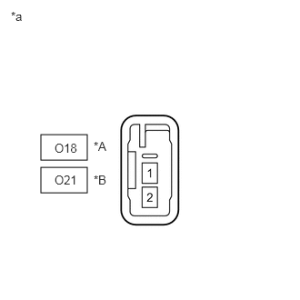
0.469,1.917 1,2.208 0.531,0.292 0.469,1.542 1,1.833 0.531,0.292 0.625,1.979 1.167,2.323 0.542,0.344 10 false O21 0.625,1.615 1.156,1.927 0.531,0.313 10 false O18 0.125,0.104 0.542,0.427 0.417,0.323 10 false *a 1.073,1.594 1.438,1.917 0.365,0.323 10 false *A 1.073,1.979 1.469,2.354 0.396,0.375 10 false *B
*A for RH
*B for LH
*a Component without harness connected
(Rear Speaker Assembly)


Measure the resistance according to the value(s) in the table below.

Standard Resistance:
Tester Connection Condition Specified Condition
O18-1 - O18-2 Always 3.2 to 4.8 Ω
O21-1 - O21-2 Always 3.2 to 4.8 Ω


Result:
Proceed to
OK
NG


OK

REPLACE RADIO AND DISPLAY RECEIVER ASSEMBLY

NG