PARKING BRAKE PARKING BRAKE ASSEMBLY REASSEMBLY
PROCEDURE

 1.INSTALL PARKING BRAKE SHOE LEVER
Install the parking brake shoe lever.
2.INSTALL DUST COVER
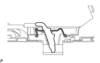
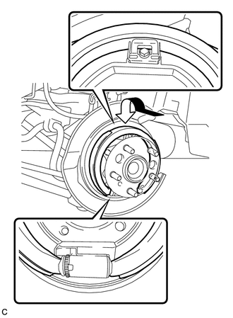
Install the dust cover to the parking brake shoe lever as shown in the illustration.
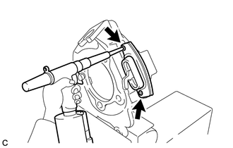
Using an air riveter or a hand riveter with a nose piece, install the boot retainer on the parking brake plate sub-assembly with 2 new rivets.
- HINT:
-
If the mandrel of the rivet does not come off on the first operation of the rivet gun, slide the rivet gun forward on the mandrel and operate it again.
- NOTICE:
- ·
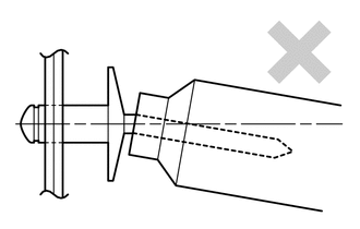
Do not pry the rivet with the riveter, as this will cause damage to the riveter and mandrel.
·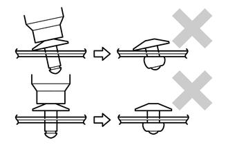
Confirm that the rivets are seated properly against the boot retainer.
·Do not tilt the riveter when installing the rivet onto the boot retainer.
·Do not leave any space between the rivet head and boot retainer.
·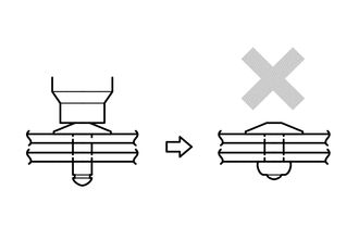
Do not leave any space between the boot retainer and the parking brake plate sub-assembly. Firmly hold the 2 items together while installing the rivet.
3.INSTALL PARKING BRAKE PLATE SUB-ASSEMBLY
Install the parking brake plate sub-assembly.
4.INSTALL DUST PLATE
Install the dust plate to the parking brake plate sub-assembly.
42450B
5.INSTALL REAR AXLE HUB AND BEARING ASSEMBLY
89516D
6.CONNECT SKID CONTROL SENSOR WIRE
7.INSTALL PARKING BRAKE SHOE HOLD PLATE
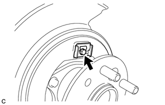
Install the parking brake shoe hold plate with a new parking brake shoe hold bolt.
- Torque:
- 9.0 N*m (92 kgf*cm, 80 in.*lbf)
8.INSTALL ADJUSTMENT PAWL
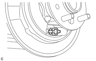
Install the adjustment pawl.
9.INSTALL NUT AND SCREW ADJUSTING ASSEMBLY
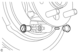

|
High Temperature Grease |
Apply high temperature grease to the parking brake plate sub-assembly as shown in the illustration.
Install the nut and screw adjusting assembly, parking brake tappet and parking brake push rod.
46430
10.CONNECT NO. 3 PARKING BRAKE CABLE ASSEMBLY
11.INSTALL PARKING BRAKE SHOE ASSEMBLY
Install the parking brake shoe assembly as shown in the illustration.
- NOTICE:
-
There should be no oil or grease on the friction surface of the lining and disc.
12.INSPECT REAR AXLE HUB BEARING LOOSENESS
13.INSPECT REAR AXLE HUB RUNOUT
42431
14.INSTALL REAR DISC
42491
15.INSTALL PARKING BRAKE SHOE ADJUSTING HOLE PLUG
16.INSTALL REAR DISC BRAKE CALIPER ASSEMBLY
17.INSTALL REAR WHEEL
- Torque:
- 103 N*m (1049 kgf*cm, 76 ft.*lbf)
18.ADJUST PARKING BRAKE SHOE CLEARANCE AND PARKING BRAKE PEDAL TRAVEL (for LHD)
19.ADJUST PARKING BRAKE SHOE CLEARANCE AND PARKING BRAKE PEDAL TRAVEL (for RHD)