STEERING COLUMN STEERING COLUMN ASSEMBLY INSTALLATION
PROCEDURE

 45220
1.INSTALL STEERING INTERMEDIATE SHAFT ASSEMBLY
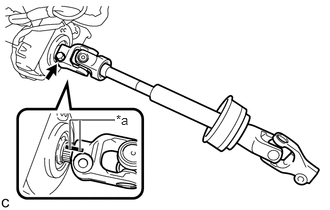
| *a | Matchmark |
Install the steering intermediate shaft assembly to the steering column assembly.
- NOTICE:
-
Align the matchmarks on the steering intermediate shaft assembly and the steering column assembly.
Install the bolt.
- Torque:
- 35 N*m (360 kgf*cm, 26 ft.*lbf)
2.INSTALL STEERING POST ASSEMBLY
Install the steering post assembly with the 4 nuts.
- Torque:
- 25 N*m (255 kgf*cm, 18 ft.*lbf)
Install the ground wire with the bolt.
- Torque:
- 8.4 N*m (85 kgf*cm, 74 in.*lbf)
Engage the clamp.
Connect the 2 connectors.
Connect the connectors and engage the wire harness clamps to the steering post assembly.
87201B
3.INSTALL NO. 2 AIR DUCT SUB-ASSEMBLY (for LHD)
Engage the clamp to install the No. 2 air duct sub-assembly.
Engage the 2 claws and guide.
87201B
4.INSTALL NO. 2 AIR DUCT SUB-ASSEMBLY (for RHD)
Engage the 2 claws to install the No. 2 air duct sub-assembly.
Install the bolt.
- Torque:
- 9.8 N*m (100 kgf*cm, 87 in.*lbf)
45220
5.CONNECT STEERING INTERMEDIATE SHAFT ASSEMBLY
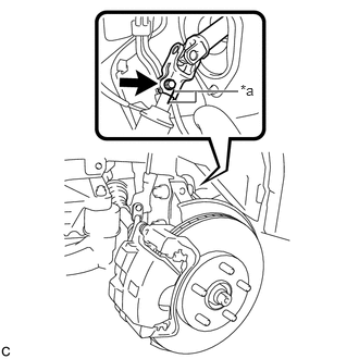
| *a | Matchmark |
Connect the steering intermediate shaft assembly to the steering link assembly.
- NOTICE:
-
Align the matchmarks on the steering intermediate shaft assembly and the steering link assembly.
Install the bolt.
- Torque:
- 35 N*m (360 kgf*cm, 26 ft.*lbf)
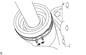
Tighten the clamp.
6.INSTALL TURN SIGNAL SWITCH ASSEMBLY WITH SPIRAL CABLE SUB-ASSEMBLY
- NOTICE:
- ·
Do not replace the spiral cable with sensor sub-assembly with the battery connected and the ignition switch to ON.
·Do not rotate the spiral cable with sensor sub-assembly without the steering wheel with the battery connected and the ignition switch to ON.
·Ensure that the steering wheel is installed and aligned straight when inspecting the steering sensor.
Engage the 3 claws to install the turn signal switch assembly with spiral cable sub-assembly to the steering post assembly.
Connect the connectors to the turn signal switch assembly with spiral cable sub-assembly.
45286B
7.INSTALL UPPER STEERING COLUMN COVER
Engage the 2 claws to install the upper steering column cover.
Engage the 4 clips and 2 guides to the upper steering column cover.
45287
8.INSTALL LOWER STEERING COLUMN COVER
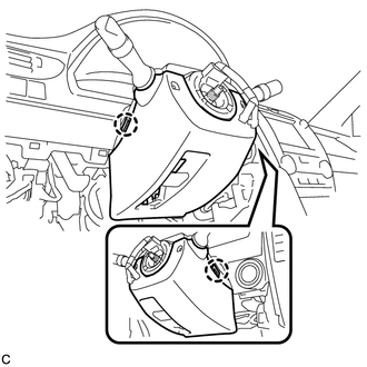
Engage the 2 claws to install the lower steering column cover.
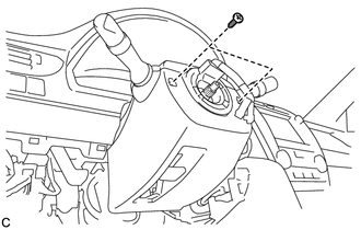
Install the 2 screws.
- Torque:
- 2.0 N*m (20 kgf*cm, 18 in.*lbf)
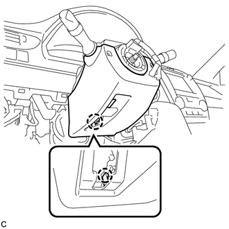
Engage the claw.
53601
9.CONNECT HOOD LOCK CONTROL LEVER SUB-ASSEMBLY (for LHD)
55432D
10.INSTALL LOWER NO. 1 INSTRUMENT PANEL FINISH PANEL ASSEMBLY (for LHD)
55318C
11.INSTALL INSTRUMENT SIDE PANEL LH (for LHD)
62312B
12.INSTALL FRONT DOOR OPENING TRIM WEATHERSTRIP LH (for LHD)
62112A
13.INSTALL COWL SIDE TRIM SUB-ASSEMBLY LH (for LHD)
67914B
14.INSTALL FRONT DOOR SCUFF PLATE LH (for LHD)
73900
15.INSTALL LOWER NO. 1 INSTRUMENT PANEL AIRBAG ASSEMBLY (for RHD)
16.TURN FRONT WHEELS TO FACE STRAIGHT AHEAD
17.INSPECT AND ADJUST SPIRAL CABLE SUB-ASSEMBLY
45100
18.INSTALL STEERING WHEEL ASSEMBLY
19.INSPECT STEERING WHEEL CENTER POINT
45130
20.INSTALL HORN BUTTON ASSEMBLY
21.INSTALL FRONT WHEEL
- Torque:
- 103 N*m (1049 kgf*cm, 76 ft.*lbf)