 |
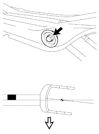
Temporarily tighten the rear No. 1 suspension arm assembly LH (inner side) with the bolt.
 | Bolt |
 | Front of the Vehicle |
 | Paint Mark |
- HINT:
- Ensure that the paint mark faces the rear of the vehicle.
REAR LOWER ARM > INSTALLATION |
| 1. INSTALL REAR NO. 1 SUSPENSION ARM ASSEMBLY LH |
|
Temporarily tighten the rear No. 1 suspension arm assembly LH (inner side) with the bolt.
| Bolt |
| Front of the Vehicle |
| Paint Mark |
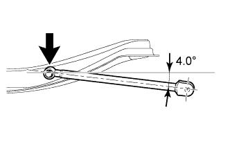 |
Set the rear No.1 suspension arm assembly in the position shown in the illustration, and fully tighten the bolt.
| 2. INSTALL REAR NO. 1 SUSPENSION ARM ASSEMBLY RH |
| 3. TEMPORARILY TIGHTEN REAR NO. 2 SUSPENSION ARM ASSEMBLY LH |
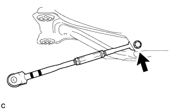 |
Temporarily tighten the rear No. 2 suspension arm assembly LH (inside) with the bolt.
| Bolt |
| Paint Mark |
| 4. INSTALL REAR SUSPENSION MEMBER SUB-ASSEMBLY |
| 5. TEMPORARILY TIGHTEN REAR NO. 2 SUSPENSION ARM ASSEMBLY RH |
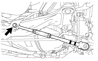 |
Temporarily tighten the rear No. 2 suspension arm assembly RH (inside) with the bolt.
| Bolt |
| Paint Mark |
| 6. CONNECT REAR NO. 2 SUSPENSION ARM ASSEMBLY RH |
Connect the rear No. 2 suspension arm assembly RH (outer side) to the rear axle carrier sub-assembly with the bolt and nut.
| 7. STABILIZE SUSPENSION |
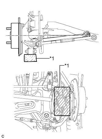 |
Jack up the rear axle carrier sub-assembly, placing a wooden block under it to avoid damage. Apply load to the suspension so that the installed bolt of the rear No. 1 suspension arm assembly (inner side) is horizontally aligned with the center of the rear axle hub.
| *1 | Wooden Block |
| 8. FULLY TIGHTEN REAR NO. 2 SUSPENSION ARM ASSEMBLY RH |
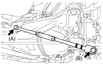 |
Fully tighten the bolt (A).
Fully tighten the bolt (B).
| 9. INSTALL REAR HEIGHT CONTROL SENSOR SUB-ASSEMBLY (w/ Height Control Sensor) |
| 10. INSTALL REAR WHEELS |
| 11. INSPECT AND ADJUST REAR WHEEL ALIGNMENT |
| 12. INITIALIZE HEIGHT CONTROL SENSOR SIGNAL (w/ Height Control Sensor) |
| 13. ADJUST HEADLIGHT AIMING (w/ Height Control Sensor) |