AUTOMATIC TRANSAXLE ASSEMBLY > INSTALLATION |
| 1. INSPECT TORQUE CONVERTER ASSEMBLY |
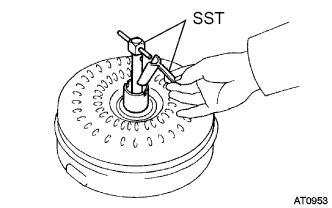
Inspect the one-way clutch.
![]() |
Set SST into the inner race of the one-way clutch.
Install SST so that it fits in the notch of the torque converter assembly hub and the outer race of the one-way clutch.
![]() |
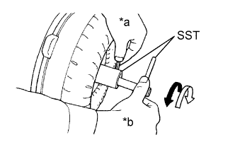
Stand the torque converter assembly up and turn SST.
| *a | Hold |
| *b | Turn |
![]() | Lock |
![]() | Smooth |
![]() |
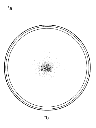
Inspect the torque converter assembly.
If any of the following problems are present, replace the torque converter assembly.
| *a | Sample showing maximum allowable amount of powder in ATF |
| *b | Full Scale |
Replace the ATF in the torque converter assembly.
![]() |
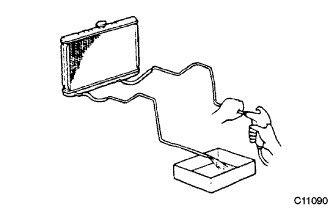
Clean and check the oil cooler and oil pipe line.
![]() |
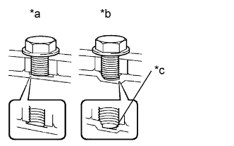
Prevent deformation of the torque converter assembly and damage to the oil pump gear.
| *a | Correct |
| *b | Incorrect |
| *c | Bottom is damaged |
| 2. INSTALL TORQUE CONVERTER ASSEMBLY |
![]() |
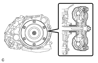
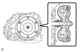
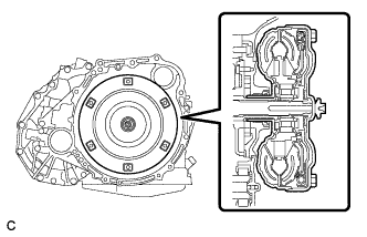
Engage the splines of the input shaft and turbine runner.
![]() |
Engage the splines of the stator shaft and the stator while turning the torque converter assembly.
![]() |
Turn the torque converter assembly to insert the key of the oil pump drive gear into the groove of the torque converter assembly.
Clean the torque converter assembly set bolt holes.
![]() |
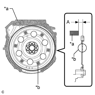
Using a vernier caliper and straightedge, measure dimension A between the transaxle contact surface of the engine *a and the torque converter assembly contact surface of the drive plate *b.
| *a | Engine Surface |
| *b | Drive Plate Surface |
![]() |
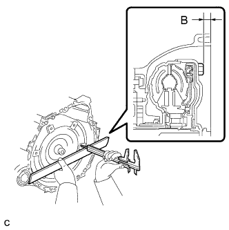
Using a vernier caliper and straightedge, measure dimension B shown in the illustration and check that dimension B is more than dimension A, which was measured in the previous step.
| 3. INSTALL SPEEDOMETER DRIVEN HOLE COVER SUB-ASSEMBLY |
Coat a new O-ring with ATF and install it to the speedometer driven hole cover sub-assembly.
Install the speedometer driven hole cover sub-assembly to the automatic transaxle assembly with the bolt.
| 4. INSTALL TRANSMISSION OIL FILLER TUBE SUB-ASSEMBLY |
Coat a new O-ring with ATF and install it to the transmission oil filler tube sub-assembly.
Install the transmission oil filler tube sub-assembly to the automatic transaxle assembly with the bolt.
Install the transmission oil level gauge sub-assembly to the transmission oil filler tube sub-assembly.
| 5. INSTALL WIRE HARNESS CLAMP BRACKET |
Install the 2 wire harness clamp brackets to the automatic transaxle assembly with the 2 bolts.
| 6. INSTALL NO. 2 TRANSMISSION CONTROL CABLE BRACKET |
Install the No. 2 transmission control cable bracket to the automatic transaxle assembly with the bolt.
| 7. INSTALL NO. 1 TRANSMISSION CONTROL CABLE BRACKET |
Install the No. 1 transmission control cable bracket to the automatic transaxle assembly with the 2 bolts.
| 8. INSTALL NO. 1 FLEXIBLE HOSE CLAMP |
Install the No. 1 flexible hose clamp to the No. 1 transmission control cable bracket with the bolt.
| 9. INSTALL FRONT ENGINE MOUNTING BRACKET |
Install the front engine mounting bracket to the automatic transaxle assembly with the 3 bolts.
| 10. INSTALL AUTOMATIC TRANSAXLE ASSEMBLY |
![]() |
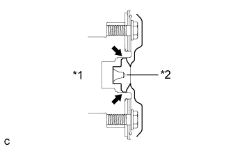
Apply clutch spline grease to the surface of the crankshaft that contacts the torque converter assembly centerpiece.
| *1 | Crankshaft |
| *2 | Torque Converter Assembly Centerpiece |
![]() |
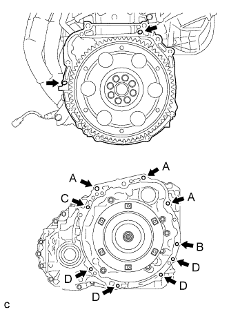
While keeping the engine and automatic transaxle assembly horizontal, align the knock pins with the holes in the automatic transaxle assembly and install the 9 bolts shown in the illustration.
| 11. INSTALL FRONT FRAME ASSEMBLY |
Install the engine mounting insulator LH to the automatic transaxle assembly with the nut.
Install the engine mounting insulator RH to the engine with the nut.
Install the front engine mounting insulator to the automatic transaxle assembly with the bolt.
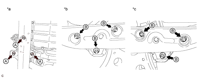
Fully tighten the 9 temporarily installed nuts of the engine mounting insulators to the specified torque.

| *a | Front Engine Mounting Insulator Side | *b | Engine Mounting Insulator RH Side |
| *c | Engine Mounting Insulator LH Side | - | - |
Install the 4 hole plugs.
| 12. INSTALL ENGINE WIRE |
Connect the 4 connectors and 6 clamps, and install the engine wire to the automatic transaxle assembly with the bolt.
| 13. INSTALL ENGINE ASSEMBLY WITH TRANSAXLE |
| 14. RESET MEMORY |