 |
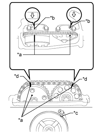
Turn the crankshaft pulley until its groove and the timing mark "0" of the timing chain cover sub-assembly are aligned.
| *a | Timing Mark |
| *b | Front Mark |
| *c | Groove |
| *d | Paint Mark |
VALVE CLEARANCE > ADJUSTMENT |
| 1. REMOVE CYLINDER HEAD COVER SUB-ASSEMBLY |
| 2. SET NO. 1 CYLINDER TO TDC/COMPRESSION |
|
Turn the crankshaft pulley until its groove and the timing mark "0" of the timing chain cover sub-assembly are aligned.
| *a | Timing Mark |
| *b | Front Mark |
| *c | Groove |
| *d | Paint Mark |
Check that each timing mark of the camshaft timing gear assembly and camshaft timing sprocket is aligned with each front mark located on the No. 1 and No. 2 bearing caps as shown in the illustration.
If not, turn the crankshaft by 1 revolution (360°) to align the timing marks as above.
Place paint marks on the chain sub-assembly in alignment with the timing marks on the camshaft timing gear assembly and camshaft timing sprocket.
| 3. CHECK VALVE CLEARANCE |
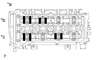 |
Check only the valves indicated.
| *a | No. 1 Cylinder TDC/Compression |
| *b | Intake Side |
| *c | Exhaust Side |
Using a feeler gauge, measure the clearance between the valve lifter and camshaft.
| Item | Specified Condition |
| Intake | 0.19 to 0.29 mm (0.00748 to 0.0114 in.) |
| Exhaust | 0.38 to 0.48 mm (0.0150 to 0.0189 in.) |
Record any out-of-specification valve clearance measurements. They will be used later to determine the required replacement valve lifters.
Turn the crankshaft 1 revolution (360°) and set the No. 4 cylinder to TDC/compression.
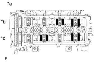 |
Check only the valves indicated.
| *a | No. 4 Cylinder TDC/Compression |
| *b | Intake Side |
| *c | Exhaust Side |
Using a feeler gauge, measure the clearance between the valve lifter and camshaft.
| Item | Specified Condition |
| Intake | 0.19 to 0.29 mm (0.00748 to 0.0114 in.) |
| Exhaust | 0.38 to 0.48 mm (0.0150 to 0.0189 in.) |
Record any out-of-specification valve clearance measurements. They will be used later to determine the required replacement valve lifters.
| 4. ADJUST VALVE CLEARANCE |
Remove the camshaft (Click here).
Remove the valve lifters.
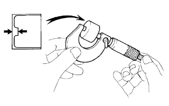 |
Using a micrometer, measure the thickness of the removed valve lifters.
Calculate the thickness of a new lifter so that the valve clearance comes within the specified range.
| Item | Specification |
| Intake | A = B + (C - 0.24 mm (0.00945 in.)) |
| Exhaust | A = B + (C - 0.43 mm (0.0169 in.)) |
| A | New lifter thickness |
| B | Used lifter thickness |
| C | Measured valve clearance |
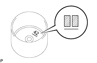 |
Select a new lifter with a thickness as close as possible to the calculated values.
Valve lifter selection chart (intake).
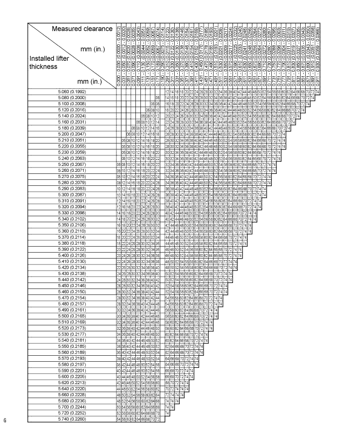
| Lifter No. | Thickness mm (in.) | Lifter No. | Thickness mm (in.) | Lifter No. | Thickness mm (in.) |
| 06 | 5.060 (0.1992) | 30 | 5.300 (0.2087) | 54 | 5.540 (0.2181) |
| 08 | 5.080 (0.2000) | 32 | 5.320 (0.2094) | 56 | 5.560 (0.2189) |
| 10 | 5.100 (0.2008) | 34 | 5.340 (0.2102) | 58 | 5.580 (0.2197) |
| 12 | 5.120 (0.2016) | 36 | 5.360 (0.2110) | 60 | 5.600 (0.2205) |
| 14 | 5.140 (0.2024) | 38 | 5.380 (0.2118) | 62 | 5.620 (0.2213) |
| 16 | 5.160 (0.2031) | 40 | 5.400 (0.2126) | 64 | 5.640 (0.2220) |
| 18 | 5.180 (0.2039) | 42 | 5.420 (0.2134) | 66 | 5.660 (0.2228) |
| 20 | 5.200 (0.2047) | 44 | 5.440 (0.2142) | 68 | 5.680 (0.2236) |
| 22 | 5.220 (0.2055) | 46 | 5.460 (0.2150) | 70 | 5.700 (0.2244) |
| 24 | 5.240 (0.2063) | 48 | 5.480 (0.2157) | 72 | 5.720 (0.2252) |
| 26 | 5.260 (0.2071) | 50 | 5.500 (0.2165) | 74 | 5.740 (0.2260) |
| 28 | 5.280 (0.2079) | 52 | 5.520 (0.2173) | - | - |
Valve lifter selection chart (exhaust).
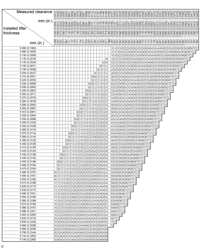
| Lifter No. | Thickness mm (in.) | Lifter No. | Thickness mm (in.) | Lifter No. | Thickness mm (in.) |
| 06 | 5.060 (0.1992) | 30 | 5.300 (0.2087) | 54 | 5.540 (0.2181) |
| 08 | 5.080 (0.2000) | 32 | 5.320 (0.2094) | 56 | 5.560 (0.2189) |
| 10 | 5.100 (0.2008) | 34 | 5.340 (0.2102) | 58 | 5.580 (0.2197) |
| 12 | 5.120 (0.2016) | 36 | 5.360 (0.2110) | 60 | 5.600 (0.2205) |
| 14 | 5.140 (0.2024) | 38 | 5.380 (0.2118) | 62 | 5.620 (0.2213) |
| 16 | 5.160 (0.2031) | 40 | 5.400 (0.2126) | 64 | 5.640 (0.2220) |
| 18 | 5.180 (0.2039) | 42 | 5.420 (0.2134) | 66 | 5.660 (0.2228) |
| 20 | 5.200 (0.2047) | 44 | 5.440 (0.2142) | 68 | 5.680 (0.2236) |
| 22 | 5.220 (0.2055) | 46 | 5.460 (0.2150) | 70 | 5.700 (0.2244) |
| 24 | 5.240 (0.2063) | 48 | 5.480 (0.2157) | 72 | 5.720 (0.2252) |
| 26 | 5.260 (0.2071) | 50 | 5.500 (0.2165) | 74 | 5.740 (0.2260) |
| 28 | 5.280 (0.2079) | 52 | 5.520 (0.2173) | - | - |
Install the selected valve lifter.
Install the camshaft (Click here).
| 5. INSTALL CYLINDER HEAD COVER SUB-ASSEMBLY |