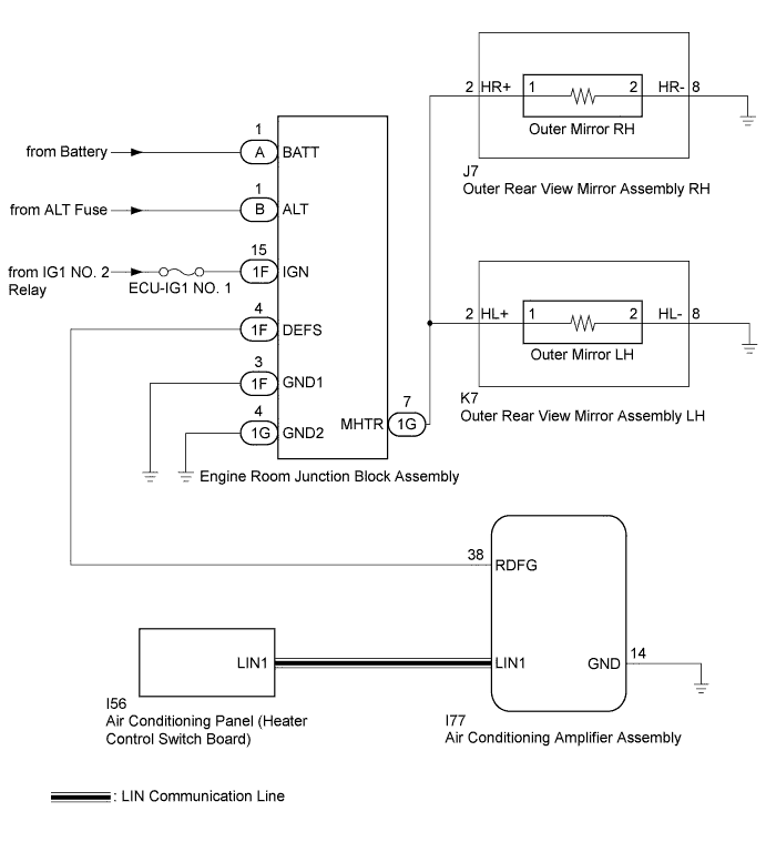
POWER MIRROR CONTROL SYSTEM > Mirror Heater does not Operate with Rear Defogger Switch |
| 1.PERFORM ACTIVE TEST USING INTELLIGENT TESTER |
Connect the intelligent tester to the DLC3.
Turn the ignition switch to ON.
Turn the intelligent tester on.
Enter the following menus: Body / Air Conditioner / Active Test.
Perform an Active Test according to the display on the intelligent tester.
| Tester Display | Test Part | Control Range | Diagnostic Note |
| Defogger Relay (Rear) | Mirror heater | OFF/ON | - |
| Result | Proceed to |
| Mirror heater operations on both mirrors are not normal | A |
| Mirror heater operation on RH side mirror is not normal | B |
| Mirror heater operation on LH side mirror is not normal | C |
|
| ||||
|
| ||||
| A | |
 |
| 2.CHECK REAR WINDOW DEFOGGER SYSTEM |
Check the rear window defogger operation (Click here).
|
| ||||
| OK | |
|
| 3.CHECK ENGINE ROOM JUNCTION BLOCK ASSEMBLY |
Using a voltmeter, check the waveform of the engine room junction block assembly (Click here).
|
| ||||
| OK | |
|
| 4.CHECK HARNESS AND CONNECTOR (ENGINE ROOM JUNCTION BLOCK ASSEMBLY - POWER SOURCE AND BODY GROUND) |
Remove the engine room junction block assembly from the engine room relay block and junction block assembly.
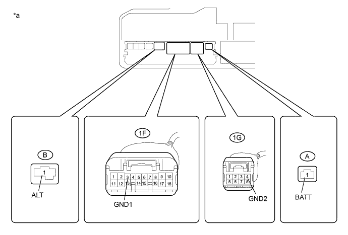
Measure the voltage according to the value(s) in the table below.
| Tester Connection | Condition | Specified Condition |
| A-1 (BATT) - Body ground | Always | 11 to 14 V |
| B-1 (ALT) - Body ground | Always | 11 to 14 V |
Measure the resistance according to the value(s) in the table below.
| Tester Connection | Condition | Specified Condition |
| 1F-3 (GND1) - Body ground | Always | Below 1 Ω |
| 1G-4 (GND2) - Body ground | Always | Below 1 Ω |
| *a | Component without engine room junction block assembly (Engine Room Relay Block and Junction Block Assembly) | - | - |
|
| ||||
| OK | |
|
| 5.CHECK HARNESS AND CONNECTOR (OUTER REAR VIEW MIRROR ASSEMBLY - ENGINE ROOM JUNCTION BLOCK ASSEMBLY) |
Disconnect the 1G connector from the engine room junction block assembly.
Disconnect the J7 connector from the outer rear view mirror assembly RH.
Disconnect the K7 connector from the outer rear view mirror assembly LH.
Measure the resistance according to the value(s) in the table below
| Tester Connection | Condition | Specified Condition |
| 1G-7 (MHTR) - J7-2 (HR+) | Always | Below 1 Ω |
| 1G-7 (MHTR) - K7-2 (HL+) | Always | Below 1 Ω |
|
| ||||
| OK | ||
 | ||
| ||
| 6.CHECK HARNESS AND CONNECTOR (ENGINE ROOM JUNCTION BLOCK ASSEMBLY - OUTER REAR VIEW MIRROR ASSEMBLY RH - BODY GROUND) |
Disconnect the 1G connector from the engine room junction block assembly .
Disconnect the J7 connector from the outer rear view mirror assembly RH.
Measure the resistance according to the value(s) in the table below.
| Tester Connection | Condition | Specified Condition |
| 1G-7 (MHTR) - J7-2 (HR+) | Always | Below 1 Ω |
| J7-8 (HR-) - Body Ground | Always | Below 1 Ω |
|
| ||||
| OK | |
|
| 7.INSPECT OUTER MIRROR RH |
Remove the outer mirror RH (Click here).
Inspect the outer mirror RH (Click here).
|
| ||||
| OK | ||
| ||
| ||
| 8.CHECK HARNESS AND CONNECTOR (ENGINE ROOM JUNCTION BLOCK ASSEMBLY - OUTER REAR VIEW MIRROR ASSEMBLY LH - BODY GROUND) |
Disconnect the 1G connector from the engine room junction block assembly.
Disconnect the K7 connector from the outer rear view mirror assembly LH.
Measure the resistance according to the value(s) in the table below.
| Tester Connection | Condition | Specified Condition |
| 1G-7 (MHTR) - K7-2 (HL+) | Always | Below 1 Ω |
| K7-8 (HL-) - Body Ground | Always | Below 1 Ω |
|
| ||||
| OK | |
|
| 9.INSPECT OUTER MIRROR LH |
Remove the outer mirror LH (Click here).
Inspect the outer mirror LH (Click here).
|
| ||||
| OK | ||
| ||
| ||

