 |
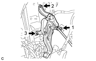
Install the parking brake control pedal assembly with the bolt and 2 nuts.
- Torque:
- 15 N*m{ 153 kgf*cm , 11 ft.*lbf }
- NOTICE:
- Tighten the bolt and 2 nuts in the order shown in the illustration.
PARKING BRAKE PEDAL (for LHD) > INSTALLATION |
| 1. INSTALL PARKING BRAKE CONTROL PEDAL ASSEMBLY |
|
Install the parking brake control pedal assembly with the bolt and 2 nuts.
Connect the parking brake switch connector.
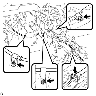 |
Install the No. 1 parking brake cable assembly with the bolt and 2 nuts.
Install the clip to the No. 1 parking brake cable assembly.
Install the floor carpet.
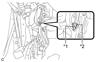 |
Temporarily install the lock nut.
| *1 | Lock Nut |
| *2 | Adjusting Nut |
| 2. CONNECT NO. 4 PARKING BRAKE CABLE ASSEMBLY |
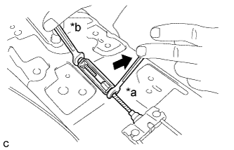 |
Connect the No. 4 parking brake cable assembly to the parking brake control pedal assembly as shown in the illustration.
| *a | Turn |
| *b | Hold |
| 3. INSTALL AIRBAG SENSOR ASSEMBLY |
Check that the ignition switch is off.
Check that the cable is disconnected from the negative (-) battery terminal.
Using SST, install the airbag sensor assembly with the 3 bolts.
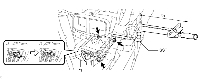
| *1 | Waterproof Sheet | - | - |
| *a | Fulcrum Length | - | - |
Connect the connectors to the airbag sensor assembly as shown in the illustration.
Check that the waterproof sheet is properly set.
Check that there is no looseness in the installation parts of the airbag sensor assembly.
| 4. INSTALL FLOOR CARPET BRACKET RH |
Engage the 2 guides.
Install the floor carpet bracket RH with the 2 clips.
| 5. INSTALL NO. 1 INDOOR ELECTRICAL KEY ANTENNA ASSEMBLY (w/ Smart Entry and Start System) |
Connect the connector.
Install the No. 1 indoor electrical key antenna assembly with the bolt.
Engage the clamp.
| 6. INSTALL LOWER NO. 1 INSTRUMENT PANEL AIRBAG ASSEMBLY (w/ Driver Side Knee Airbag) |
Check that the ignition switch is off.
Check that the cable is disconnected from the negative (-) battery terminal.
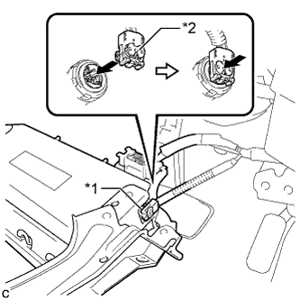 |
Connect the airbag connector to the lower No. 1 instrument panel airbag assembly.
| *1 | Airbag Connector |
| *2 | Airbag Connector Lock |
Push in the lock to install the airbag connector.
Temporarily install the lower No. 1 instrument panel airbag assembly with the 2 hooks.
Engage the 2 claws to install the DLC3.
Install the 4 bolts.
| 7. INSTALL SHIFT LEVER SUPPORT |
| 8. CONNECT CABLE TO NEGATIVE BATTERY TERMINAL |
| 9. PERFORM DIAGNOSTIC SYSTEM CHECK |
| 10. INSPECT SRS WARNING LIGHT |
| 11. ADJUST PARKING BRAKE PEDAL TRAVEL |
Completely release the parking brake pedal.
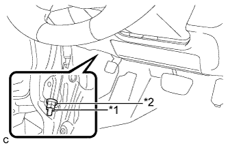 |
Loosen the lock nut and the adjusting nut to completely release the parking brake cable.
| *1 | Lock Nut |
| *2 | Adjusting Nut |
Remove the rear wheels.
Temporarily install the hub nuts to the hub bolts.
Remove the parking brake shoe adjusting hole plug.
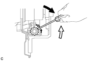 |
Turn the shoe adjuster and expand the shoes until the disc locks.
 | Expand |
 | Contract |
Turn and contract the shoe adjuster until the disc can rotate smoothly.
Check that there is no brake drag against the shoes.
Install the parking brake shoe adjusting hole plug.
Turn the adjusting nut until the parking brake pedal travel is corrected to be within the specified range.
Using a wrench or an equivalent tool, hold the adjusting nut and tighten the lock nut.
Operate the parking brake pedal 3 to 4 times, and check the parking brake pedal travel.
Check that the parking brake does not drag.
Remove the hub nuts from the hub bolts.
Install the rear wheels.
| 12. INSPECT BRAKE WARNING LIGHT |
When operating the parking brake pedal, check that the brake warning light illuminates.