Home › Drivetrain · U241E AUTOMATIC TRANSMISSION / TRANSAXLE › AUTOMATIC TRANSAXLE SYSTEM

DTC    P2714    Pressure Control Solenoid "D" Performance (Shift Solenoid Valve SLT)

for Preparation Click here


SYSTEM DESCRIPTION

The linear solenoid valve (SLT) controls the transmission line pressure for smooth transmission operation based on signals from the throttle position sensor and the vehicle speed sensor. The ECM adjusts the duty ratio of the SLT solenoid valve to control hydraulic line pressure coming from the primary regulator valve. Appropriate line pressure assures smooth shifting with varying engine outputs.

DTC No.
DTC Detection Condition
Trouble Area
P2714
ECM detects a malfunction on SLT (ON side) according to the revolution difference of the turbine, intermediate and the output shaft, and also by the oil pressure. (2-trip detection logic)
  1. Shift solenoid valve SLT remains closed
  2. Valve body is blocked
  3. Automatic transaxle (clutch, brake or gear etc.)

MONITOR DESCRIPTION

In any forward position, when the difference between the revolutions of the turbine, Intermediate and output shaft exceeds the specified value (varies with Intermediate, output speed) determined by the ECM, the ECM illuminates the MIL and stores the DTC.
When shift solenoid valve SLT remains on, the oil pressure goes down and the clutch engagement force decreases.

NOTICE:
If you continue driving under these conditions, the clutch will burn out and the vehicle will no longer be drivable.


INSPECTION PROCEDURE

1.CHECK OTHER DTCS OUTPUT (IN ADDITION TO DTC P2714)
  1. Connect the Intelligent tester to the DLC3.

  1. Turn the ignition switch to ON and turn the Intelligent tester main switch on.

  1. Select the item "Enter / Powertrain / Engine and ECT / Trouble Codes".

  1. Read the DTCs using the Intelligent tester.

    Result:

    Display (DTC output)
    Proceed to
    Only "P2714" is output
    A
    "P2714" and other DTCs
    B

    HINT:
    If any other codes besides "P2714" are output, perform the troubleshooting for those DTCs first.


B
GO TO DTC CHART (Click here)
A


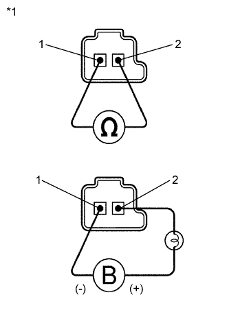
2.INSPECT SHIFT SOLENOID VALVE SLT


    G101332E01
  1. Remove the shift solenoid valve SLT.

  1. Measure the resistance according to the value(s) in the table below.

    Standard Resistance:
    Tester Connection
    Condition
    Specified Condition
    1 - 2
    20°C (68°F)
    5.0 to 5.6 Ω

  1. Connect the positive (+) lead with a 21 W bulb to terminal 2 and the negative (-) lead to terminal 1 of the solenoid valve connector, then check the movement of the valve.

    OK:
    The solenoid makes an operating sound.

    Text in Illustration 
    *1
    Shift Solenoid Valve SLT


NG
REPLACE SHIFT SOLENOID VALVE SLT (Click here)
OK


3.INSPECT TRANSMISSION VALVE BODY ASSEMBLY
  1. Check the transmission valve body assembly (Click here).

OK:
There are no foreign objects on each valve.


NG
REPAIR OR REPLACE TRANSMISSION VALVE BODY ASSEMBLY (Click here)
OK


4.INSPECT TORQUE CONVERTER ASSEMBLY
  1. Check the torque converter assembly (Click here).

OK:
The torque converter assembly operates normally.


NG
REPLACE TORQUE CONVERTER ASSEMBLY (Click here)
OK

REPAIR OR REPLACE AUTOMATIC TRANSAXLE ASSEMBLY (Click here)