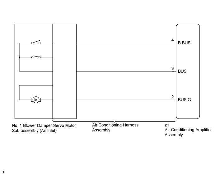
DTC B1442 Air Inlet Damper Control Servo Motor Circuit |
| DTC No. | DTC Detection Condition | Trouble Area |
| B1442 | Air inlet damper position sensor value does not change even if air conditioning amplifier assembly operates No. 1 blower damper servo sub-assembly (air inlet) |
|
| 1.READ VALUE USING TECHSTREAM |
Connect the Techstream to the DLC3.
Turn the ignition switch to ON.
Turn the Techstream on.
Operate the R/F (Recirculation/Fresh) switch.
Enter the following menus: Body Electrical / Air Conditioner / Data List.
Check the value(s) by referring to the table below.
| Tester Display | Measurement Item/Range | Normal Condition | Diagnostic Note |
| Air Inlet Damper Actual Pulse | No. 1 blower damper servo sub-assembly (air inlet) actual pulse / Min.: 0 Max.: 255 | RECIRCULATION: 7 (pulse) FRESH: 28 (pulse) | - |
| Result | Proceed to |
| NG | A |
| OK (When troubleshooting according to Problem Symptoms Table) | B |
| OK (When troubleshooting according to the DTC) | C |
|
| ||||
|
| ||||
| A | |
 |
| 2.PERFORM ACTIVE TEST USING TECHSTREAM |
Connect the Techstream to the DLC3.
Turn the ignition switch to ON.
Turn the Techstream on.
Enter the following menus: Body Electrical / Air Conditioner / Active Test.
Check the operation by referring to the table below.
| Tester Display | Test Part | Control Range | Diagnostic Note |
| Air Inlet Damper Targ Pulse | No. 1 blower damper servo sub-assembly (air inlet) pulse | Min.: 0, Max.: 255 | Operates between 7 and 28 pulses |
|
| ||||
| OK | ||
 | ||
| ||
| 3.REPLACE NO. 1 BLOWER DAMPER SERVO MOTOR SUB-ASSEMBLY (AIR INLET) |
Replace the No. 1 blower damper servo sub-assembly (air inlet) (Click here).
Check for the DTC.
| Result | Proceed to |
| DTC B1442 is output | A |
| DTC B1442 is not output | B |
|
| ||||
| A | |
|
| 4.REPLACE AIR CONDITIONING HARNESS ASSEMBLY |
Replace the air conditioning harness assembly (Click here).
Check for the DTC.
| Result | Proceed to |
| DTC B1442 is output | A |
| DTC B1442 is not output | B |
|
| ||||
| A | ||
| ||
| ||

