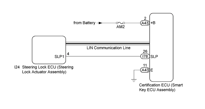
DTC B2285 Steering Lock Position Signal Circuit Malfunction |
| DTC Code | DTC Detection Condition | Trouble Area | DTC Output Confirmation Operation |
| B2285 | The steering lock position signal sent by the steering lock ECU (steering lock actuator assembly) via direct line and the steering lock position signal sent via LIN communication (1-trip detection logic*) do not match. |
| Disconnect the cable from the negative (-) battery terminal, wait 30 seconds and then reconnect the cable to the negative (-) battery terminal. Wait 40 seconds or more with the engine switch off (with the steering wheel locked), then turn the engine switch on (ACC) (with the steering unlocked) and wait 40 seconds or more. |
| Vehicle Condition when Malfunction Detected | Fail-safe Function when Malfunction Detected |
| The engine cannot be started. | The ECU does not send an engine start request. |
| DTC | Data List Item | Active Test Item |
| B2285 | Power Source Control
Smart Key
| - |
| 1.CHECK FOR DTC (LIN COMMUNICATION SYSTEM) |
Check for DTCs (Click here).
|
| ||||
| OK | |
 |
| 2.READ VALUE USING TECHSTREAM (STEERING UNLOCK SWITCH) |
Connect the Techstream to the DLC3.
Turn the engine switch on (IG).
Turn the Techstream on.
Enter the following menus: Body Electrical / Power Source Control / Data List.
According to the display on the Techstream, read the Data List.
| Tester Display | Measurement Item/Range | Normal Condition | Diagnostic Note |
| Steering Unlock Switch | State of steering unlock sensor signal output from steering lock actuator assembly/ON or OFF | ON: Steering unlocked OFF: Steering locked |
|
| Result | Proceed to |
| Data List item does not change | A |
| Data List item changes | B |
|
| ||||
| A | |
|
| 3.CHECK HARNESS AND CONNECTOR (POWER SOURCE) |
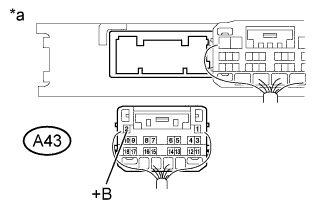 |
Disconnect the A43 connector from the certification ECU (smart key ECU assembly).
Measure the voltage according to the value(s) in the table below.
| Tester Connection | Condition | Specified Condition |
| A43-2 (+B) - Body ground | Always | 11 to 14 V |
| *a | Rear view of wire harness connector (to Certification ECU (smart key ECU assembly)) |
|
| ||||
| OK | |
|
| 4.CHECK HARNESS AND CONNECTOR (GROUND) |
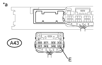 |
Measure the resistance according to the value(s) in the table below.
| Tester Connection | Condition | Specified Condition |
| A43-11 (E) - Body ground | Always | Below 1 Ω |
| *a | Rear view of wire harness connector (to Certification ECU (smart key ECU assembly)) |
|
| ||||
| OK | |
|
| 5.INSPECT STEERING LOCK ECU (STEERING LOCK ACTUATOR ASSEMBLY) |
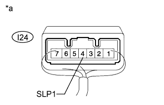 |
Measure the resistance according to the value(s) in the table below.
| Tester Connection | Condition | Specified Condition |
| Positive (+) tester probe → I24-4 (SLP1) Negative (-) tester probe → Body ground | Steering locked* | 10 kΩ or higher |
| Steering unlocked* | Below 1 Ω |
| *a | Component with harness connected (Steering Lock ECU (Steering Lock Actuator Assembly)) |
|
| ||||
| OK | |
|
| 6.CHECK HARNESS AND CONNECTOR (CERTIFICATION ECU (SMART KEY ECU ASSEMBLY) - STEERING LOCK ECU (STEERING LOCK ACTUATOR ASSEMBLY) |
Disconnect the I78 connector from the certification ECU (smart key ECU assembly).
Disconnect the I24 connector from the steering lock ECU (steering lock actuator assembly).
Measure the resistance according to the value(s) in the table below.
| Tester Connection | Condition | Specified Condition |
| I78-26 (SLP) - I24-4 (SLP1) | Always | Below 1 Ω |
| I78-26 (SLP) or I24-4 (SLP1) - Body ground | Always | 10 kΩ or higher |
|
| ||||
| OK | ||
 | ||
| ||
