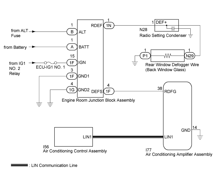
WINDOW DEFOGGER SYSTEM > Rear Window Defogger System does not Operate |
| 1.CHECK AIR CONDITIONING SYSTEM |
Check the air conditioning system.
| Result | Proceed to |
| OK | A |
| NG (for Automatic air conditioning system) | B |
| NG (for Manual air conditioning system) | C |
|
| ||||
|
| ||||
| A | |
 |
| 2.PERFORM ACTIVE TEST USING TECHSTREAM (DEFOGGER RELAY) |
Connect the Techstream to the DLC3.
Turn the ignition switch to ON.
Turn the Techstream on.
Enter the following menus: Body Electrical / Air Conditioner / Active Test.
Perform the Active Test according to the display on the Techstream.
| Tester Display | Test Part | Control Range | Diagnostic Note |
| Defogger Relay (Rear) | Rear window defogger | OFF or ON | - |
| Result | Proceed to |
| NG | A |
| OK (for Automatic air conditioning system) | B |
| OK (for Manual air conditioning system) | C |
|
| ||||
|
| ||||
| A | |
|
| 3.CHECK ENGINE ROOM JUNCTION BLOCK ASSEMBLY |
Using a voltmeter, check the signal reading of the engine room junction block assembly (Click here).
|
| ||||
| OK | |
|
| 4.CHECK HARNESS AND CONNECTOR (ENGINE ROOM JUNCTION BLOCK ASSEMBLY POWER SOURCE AND BODY GROUND) |
Remove the engine room junction block assembly from the engine room relay block and junction block assembly.
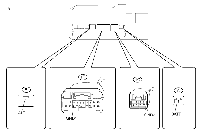
Measure the voltage according to the value(s) in the table below.
| Tester Connection | Condition | Specified Condition |
| A-1 (BATT) - Body ground | Always | 11 to 14 V |
| B-1 (ALT) - Body ground | Always | 11 to 14 V |
Measure the resistance according to the value(s) in the table below.
| Tester Connection | Condition | Specified Condition |
| 1F-3 (GND1) - Body ground | Always | Below 1 Ω |
| 1G-4 (GND2) - Body ground | Always | Below 1 Ω |
| *a | Component without engine room junction block assembly (Engine Room Relay Block and Junction Block Assembly) | - | - |
|
| ||||
| OK | |
|
| 5.CHECK HARNESS AND CONNECTOR (AIR CONDITIONING AMPLIFIER - ENGINE ROOM JUNCTION BLOCK ASSEMBLY) |
Disconnect the I77 air conditioning amplifier assembly connector.
Disconnect the 1F engine room junction block assembly connectors.
Measure the resistance according to the value(s) in the table below.
| Tester Connection | Condition | Specified Condition |
| I77-38 (RDFG) - 1F-4 (DEFS) | Always | Below 1 Ω |
| 1F-4 (DEFS) - Body ground | Always | 10 kΩ or higher |
|
| ||||
| OK | |
|
| 6.CHECK ENGINE ROOM JUNCTION BLOCK ASSEMBLY |
Reconnect the 1F engine room junction block assembly connectors.
Measure the voltage according to the value(s) in the table below.
| Tester Connection | Condition | Specified Condition |
| I77-38 (RDFG) - Body ground | Ignition switch ON | 11 to 14 V |
|
| ||||
| OK | |
|
| 7.CHECK AIR CONDITIONING AMPLIFIER ASSEMBLY |
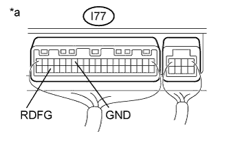 |
Reconnect the I77 air conditioning amplifier assembly connector.
Measure the voltage according to the value(s) in the table below.
| Tester Connection | Switch Condition | Specified Condition |
| I77-38 (RDFG) - I77-14 (GND) | Ignition switch ON, rear window defogger switch off | 11 to 14 V |
| I77-38 (RDFG) - I77-14 (GND) | Ignition switch ON, rear window defogger switch on | Below 2.2 V |
| *a | Component with harness connected (Air Conditioning Amplifier Assembly) |
|
| ||||
| OK | |
|
| 8.CHECK HARNESS AND CONNECTOR (ENGINE ROOM JUNCTION BLOCK ASSEMBLY - REAR WINDOW DEFOGGER WIRE) |
Disconnect the N29 rear window defogger wire (back window glass) battery side connector.
Disconnect the 1N engine room junction block assembly connector.
Measure the resistance according to the value(s) in the table below.
| Tester Connection | Condition | Specified Condition |
| 1N-1 (RDEF) - N29-1 | Always | Below 1 Ω |
|
| ||||
| OK | |
|
| 9.CHECK ENGINE ROOM JUNCTION BLOCK ASSEMBLY |
Reconnect the 1N engine room junction block assembly connector.
Measure the voltage according to the value(s) in the table below.
| Tester Connection | Switch Condition | Specified Condition |
| N29-1 - Body ground | Ignition switch ON, rear window defogger switch on | 11 to 14 V |
| N29-1 - Body ground | Ignition switch ON, rear window defogger switch off | Below 1 V |
|
| ||||
| OK | |
|
| 10.CHECK HARNESS AND CONNECTOR (REAR WINDOW DEFOGGER WIRE - BODY GROUND) |
Disconnect the P1 rear window defogger wire (back window glass) ground side connector.
Measure the resistance according to the value(s) in the table below.
| Tester Connection | Condition | Specified Condition |
| P1-1 - Body ground | Always | Below 1 Ω |
|
| ||||
| OK | ||
 | ||
| ||
