 |
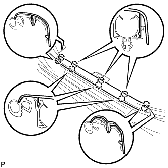
Disengage the 10 claws and remove the front door scuff plate LH.
ENGINE SWITCH > REMOVAL |
| 1. PRECAUTION |
| 2. DISCONNECT CABLE FROM NEGATIVE BATTERY TERMINAL |
| 3. REMOVE RADIO RECEIVER ASSEMBLY WITH AIR CONDITIONING CONTROL ASSEMBLY (w/o Navigation System) |
| 4. REMOVE NAVIGATION RECEIVER ASSEMBLY WITH AIR CONDITIONING CONTROL ASSEMBLY (w/ Navigation System) |
| 5. REMOVE FRONT DOOR SCUFF PLATE LH |
|
Disengage the 10 claws and remove the front door scuff plate LH.
| 6. REMOVE COWL SIDE TRIM SUB-ASSEMBLY LH |
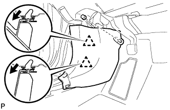 |
Remove the clip.
Disengage the 2 clips and remove the cowl side trim sub-assembly LH.
| 7. DISCONNECT FRONT DOOR OPENING TRIM WEATHERSTRIP LH |
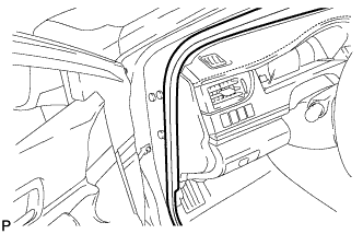 |
Disconnect the front door opening trim weatherstrip LH.
| 8. REMOVE INSTRUMENT SIDE PANEL LH |
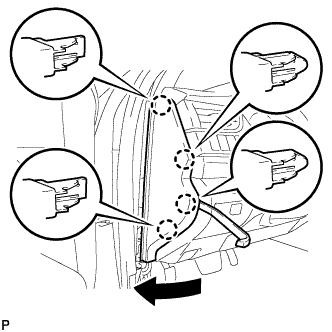 |
Using a moulding remover, disengage the 4 claws as shown in the illustration.
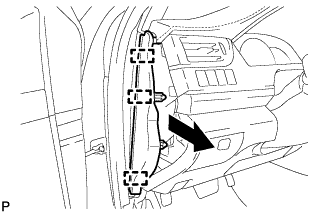 |
Disengage the 3 guides and remove the instrument side panel LH as shown in the illustration.
| 9. REMOVE NO. 1 INSTRUMENT CLUSTER FINISH PANEL GARNISH |
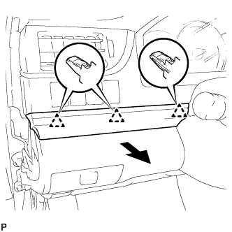 |
Disengage the 3 clips to remove the No. 1 instrument cluster finish panel garnish as shown in the illustration.
| 10. REMOVE NO. 1 INSTRUMENT PANEL REGISTER ASSEMBLY |
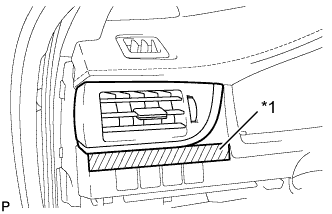 |
Apply protective tape to the area shown in the illustration.
| *1 | Protective Tape |
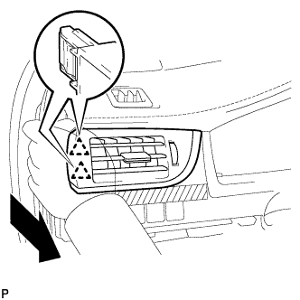 |
Disengage the 2 clips as shown in the illustration.
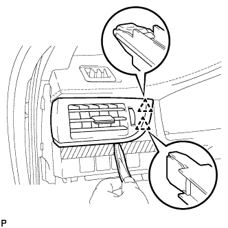 |
Using a moulding remover, disengage the 2 clips to remove the No. 1 instrument panel register assembly.
| 11. REMOVE INSTRUMENT CLUSTER FINISH PANEL ASSEMBLY |
Operate the tilt and telescopic lever to fully extend and lower the steering column assembly.
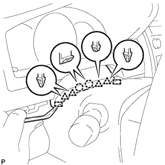 |
Using a moulding remover, disengage the 2 claws, 4 clips and 2 guides.
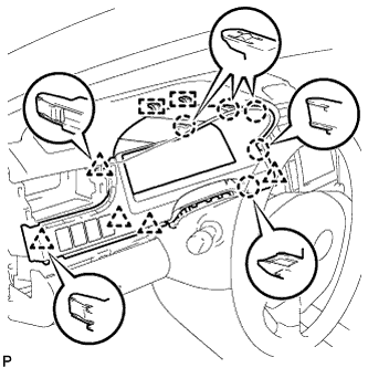 |
Disengage the 5 claws, 5 clips and 2 guides.
Disconnect each connector.
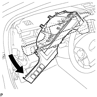 |
Remove the instrument cluster finish panel assembly as shown in the illustration.
| 12. REMOVE FRONT PANEL GARNISH LH |
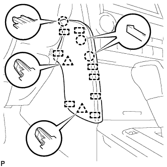 |
Disengage the 3 claws, 2 clips and 8 guides to remove the front panel garnish LH.
| 13. DISCONNECT HOOD LOCK CONTROL LEVER SUB-ASSEMBLY |
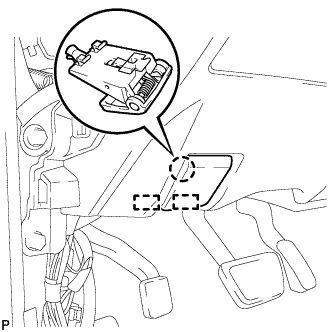 |
Disengage the claw and 2 guides to disconnect the hood lock control lever sub-assembly.
| 14. REMOVE LOWER NO. 1 INSTRUMENT PANEL FINISH PANEL ASSEMBLY |
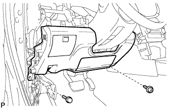 |
Remove the bolt <B> and screw <C> or <D>.
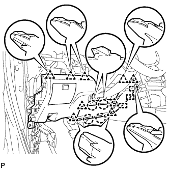 |
Disengage the 4 claws, 9 clips and 3 guides to remove the lower No. 1 instrument panel finish panel assembly.
| 15. REMOVE LOWER INSTRUMENT PANEL FINISH PANEL ASSEMBLY |
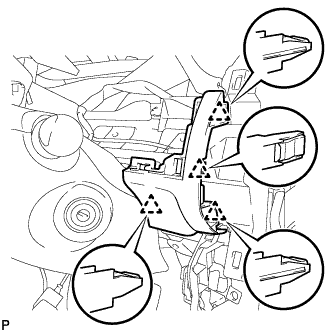 |
Disengage the 4 clips to remove the lower instrument panel finish panel assembly.
w/ Smart Key System:
Disconnect the connector.
| 16. REMOVE ENGINE SWITCH |
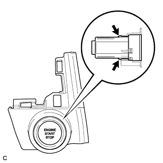 |
Disengage the 2 claws and remove the engine switch.