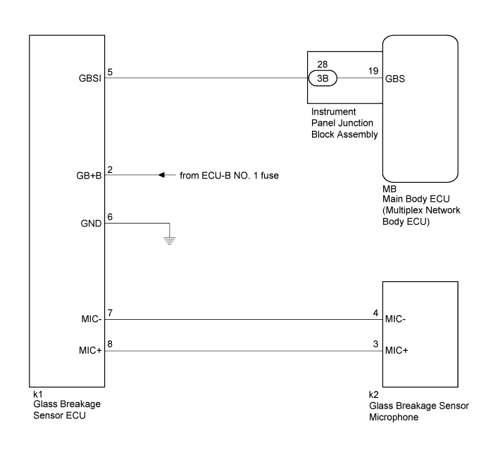
THEFT DETERRENT SYSTEM > Glass Breakage Sensor Circuit |
| 1.INSPECT INSTRUMENT PANEL JUNCTION BLOCK ASSEMBLY |
Remove the main body ECU (multiplex network body ECU) (Click here).
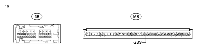
| *a | Component without harness connected (Instrument Panel Junction Block Assembly) | - | - |
Disconnect the 3B instrument panel junction block assembly connector.
Measure the resistance according to the value(s) in the table below.
| Tester Connection | Condition | Specified Condition |
| 3B-28 - MB-19 (GBS) | Always | Below 1 Ω |
|
| ||||
| OK | |
 |
| 2.CHECK HARNESS AND CONNECTOR (BATTERY - GLASS BREAKAGE SENSOR ECU - BODY GROUND) |
Disconnect the k1 glass breakage sensor ECU connector.
Measure the voltage and resistance according to the value(s) in the table below.
| Tester Connection | Condition | Specified Condition |
| k1-2 (GB+B) - Body ground | Always | 11 to 14 V |
| Tester Connection | Condition | Specified Condition |
| k1-6 (GND) - Body ground | Always | Below 1 Ω |
|
| ||||
| OK | |
|
| 3.CHECK HARNESS AND CONNECTOR (INSTRUMENT PANEL JUNCTION BLOCK ASSEMBLY - GLASS BREAKAGE SENSOR ECU) |
Measure the resistance according to the value(s) in the table below.
| Tester Connection | Condition | Specified Condition |
| k1-5 (GBSI) - 3B-28 | Always | Below 1 Ω |
| k1-5 (GBSI) - Body ground | Always | 10 kΩ or higher |
|
| ||||
| OK | |
|
| 4.CHECK HARNESS AND CONNECTOR (GLASS BREAKAGE SENSOR ECU - GLASS BREAKAGE SENSOR MICROPHONE) |
Disconnect the k2 glass breakage sensor microphone connector.
Measure the resistance according to the value(s) in the table below.
| Tester Connection | Condition | Specified Condition |
| k1-7 (MIC-) - k2-4 (MIC-) | Always | Below 1 Ω |
| k1-7 (MIC-) - Body ground | Always | 10 kΩ or higher |
| k1-8 (MIC+) - k2-3 (MIC+) | Always | Below 1 Ω |
| k1-8 (MIC+) - Body ground | Always | 10 kΩ or higher |
|
| ||||
| OK | |
|
| 5.REPLACE GLASS BREAKAGE SENSOR MICROPHONE |
Replace the glass breakage sensor microphone (Click here).
| NEXT | |
|
| 6.CHECK GLASS BREAKAGE SENSOR |
Check the operation of the glass breakage sensor (Click here).
|
| ||||
| OK | ||
 | ||
| ||
| 7.REPLACE GLASS BREAKAGE SENSOR ECU |
Replace the glass breakage sensor ECU (Click here).
| NEXT | |
|
| 8.CHECK GLASS BREAKAGE SENSOR |
Check the operation of the glass breakage sensor (Click here).
|
| ||||
| OK | ||
| ||
| ||

