Home › Steering › POWER ASSIST SYSTEMS › POWER STEERING SYSTEM › 2012.02–2015.04
RM2040EQ _55 Steering _014713 POWER ASSIST SYSTEMS _0074999 POWER STEERING SYSTEM J

POWER ASSIST SYSTEMS  POWER STEERING SYSTEM  EPS Warning Light Circuit  


DESCRIPTION

If the power steering ECU assembly detects a malfunction, the EPS warning light comes on. At this time, the power steering ECU assembly stores a DTC in its memory.

WIRING DIAGRAM
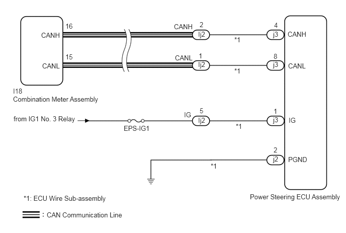
C250102E06
0.854,0.646 1.271,0.792 0.417,0.146 10 false CANH 0.875,1.281 1.271,1.427 0.396,0.146 10 false CANL 5.958,0.625 6.375,0.896 0.417,0.271 10 false CANH 5.969,1.281 6.365,1.542 0.396,0.26 10 false CANL 1.354,0.458 1.583,0.698 0.229,0.24 10 false 16 1.354,1.094 1.583,1.333 0.229,0.24 10 false 15 0.271,1.802 0.656,2.01 0.385,0.208 10 false I18 0.271,1.969 2.104,2.302 1.833,0.333 10 false Combination Meter Assembly 0.969,4.365 2.583,4.677 1.615,0.313 10 false CAN Communication Line 4.104,0.625 4.448,0.917 0.344,0.292 10 false Ij2 4.104,1.25 4.438,1.5 0.333,0.25 10 false Ij2 4.104,2.406 4.438,2.74 0.333,0.333 10 false Ij2 5.677,0.438 5.854,0.615 0.177,0.177 10 false 4 5.667,1.083 5.875,1.302 0.208,0.219 10 false 8 5.979,2.406 6.219,2.646 0.24,0.24 10 false IG 5.969,3.219 6.417,3.521 0.448,0.302 10 false PGND 5.667,3.021 5.76,3.177 0.094,0.156 10 false 2 5.177,3.99 7.125,4.417 1.948,0.427 10 false Power Steering ECU Assembly 2.563,2.573 3.448,2.719 0.885,0.146 10 false EPS-IG1 0.281,2.375 1.656,2.646 1.375,0.271 10 false from IG1 No. 3 Relay 4.135,2.208 4.271,2.427 0.135,0.219 10 false 5 5.667,2.219 5.885,2.365 0.219,0.146 10 false 1 5.656,3.208 5.781,3.531 0.125,0.323 10 false j2 5.656,2.396 5.813,2.698 0.156,0.302 10 false j3 5.656,1.25 5.813,1.563 0.156,0.313 10 false j3 5.656,0.625 5.865,0.938 0.208,0.313 10 false j3 4.135,0.427 4.271,0.677 0.135,0.25 10 false 2 4.115,1.073 4.323,1.25 0.208,0.177 10 false 1 3.604,0.469 4.052,0.719 0.448,0.25 10 false CANH 3.625,1.115 4.052,1.323 0.427,0.208 10 false CANL 3.813,2.292 4.073,2.563 0.26,0.271 10 false IG 4.885,2.531 5.219,2.75 0.333,0.219 10 false *1 4.854,0.74 5.188,0.958 0.333,0.219 10 false *1 4.854,1.385 5.188,1.604 0.333,0.219 10 false *1 4.365,3.354 4.698,3.573 0.333,0.219 10 false *1 0.49,4.021 2.646,4.292 2.156,0.271 10 false *1: ECU Wire Sub-assembly

CAUTION / NOTICE / HINT

NOTICE:

If the power steering ECU assembly has been replaced, perform assist map writing.

Click hereSteering>POWER ASSIST SYSTEMS>POWER STEERING SYSTEM>CALIBRATION


HINT:

Inspect the fuses for circuits related to this system before performing the following inspection procedure.


PROCEDURE

1.CHECK CONNECTOR CONNECTION CONDITION AND GROUND WIRE
a.

Check the connection condition of the ECU wire sub-assembly and power steering ECU assembly connectors.

OK:

The ECU wire sub-assembly and power steering ECU assembly connectors are securely connected.


b.

Check that the ground wire is securely installed with the bolt.

Click hereSteering>STEERING COLUMN>STEERING COLUMN ASSEMBLY>INSTALLATION

OK:

The ground wire is securely installed with the bolt.


Result:
Proceed to
OK
NG


OK

2.CHECK FOR DTC (CAN COMMUNICATION SYSTEM)

NG

CONNECT CONNECTOR OR INSTALL GROUND WIRE

2.CHECK FOR DTC (CAN COMMUNICATION SYSTEM)
a.

Check for DTCs.

Click herePower Source / Network>NETWORKING>CAN COMMUNICATION SYSTEM>DIAGNOSIS SYSTEM

OK:

DTC is not output.


Result:
Proceed to
OK
NG


OK

3.CHECK HARNESS AND CONNECTOR (AUXILIARY BATTERY - ECU WIRE SUB-ASSEMBLY)

NG

3.CHECK HARNESS AND CONNECTOR (AUXILIARY BATTERY - ECU WIRE SUB-ASSEMBLY)
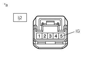
a.
C240359C04
0.458,0.458 0.906,0.74 0.448,0.281 2.531,1.083 2.156,1.219 false 0.135,0.083 0.677,0.427 0.542,0.344 10 *a 2.573,0.979 3.094,1.396 0.521,0.417 10 IG 0.604,0.521 0.969,0.938 0.365,0.417 10 Ij2
*a Front view of wire harness connector
(to ECU Wire Sub-assembly)


Disconnect the Ij2 connector from the ECU wire sub-assembly.


b.

Measure the voltage according to the value(s) in the table below.

Standard Voltage:
Tester Connection Condition Specified Condition
Ij2-5 (IG) - Body ground Power switch on (IG) 9 to 16 V


Result:
Proceed to
OK
NG


OK

4.CHECK ECU WIRE SUB-ASSEMBLY

NG

REPAIR OR REPLACE HARNESS OR CONNECTOR

4.CHECK ECU WIRE SUB-ASSEMBLY
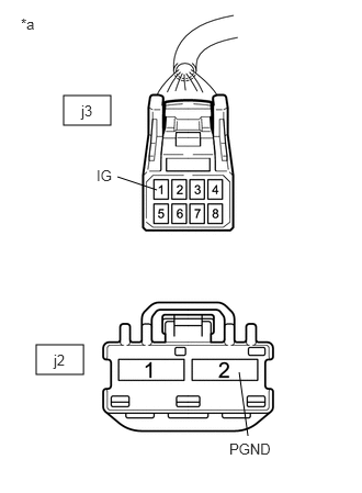
a.
C240351C06
0.344,3.271 0.792,3.552 0.448,0.281 0.604,0.906 1.052,1.188 0.448,0.281 2.271,3.531 2.354,4.135 false 1.115,1.677 1.49,1.802 false 0.198,0.146 0.635,0.458 0.438,0.313 10 false *a 0.51,3.333 0.948,3.729 0.438,0.396 10 false j2 2.177,4.177 2.906,4.51 0.729,0.333 10 false PGND 0.917,1.583 1.344,1.948 0.427,0.365 10 false IG 0.771,0.969 1.156,1.354 0.385,0.385 10 false j3
*a Front view of wire harness connector
(to Power Steering ECU Assembly)


Connect the Ij2 connector to the ECU wire sub-assembly.


b.

Disconnect the power steering ECU assembly j3 and j2 connectors.


c.

Measure the voltage according to the value(s) in the table below.

Standard Voltage:
Tester Connection Condition Specified Condition
j3-1 (IG) - Body ground Power switch on (IG) 9 to 16 V


d.

Measure the resistance according to the value(s) in the table below.

Standard Resistance:
Tester Connection Condition Specified Condition
j2-2 (PGND) - Body ground Always Below 1 Ω


Result:
Proceed to
OK
NG


OK

5.INSPECT COMBINATION METER ASSEMBLY

NG

REPAIR OR REPLACE ECU WIRE SUB-ASSEMBLY

5.INSPECT COMBINATION METER ASSEMBLY
a.

Reconnect the power steering ECU assembly connector.


b.

Perform the Active Test of the combination meter assembly using the intelligent tester.

Click hereVehicle Interior>METER / GAUGE / DISPLAY>METER / GAUGE SYSTEM>DATA LIST / ACTIVE TEST

Body Electrical > Combination Meter > Active Test
Tester Display
Indicat. EPS
50004 122 22

c.

Check the combination meter assembly.

OK:

The EPS warning light turns on or off in accordance with the intelligent tester operation.


Result:
Proceed to
OK
NG


OK

REPLACE POWER STEERING ECU ASSEMBLY

NG

REPLACE COMBINATION METER ASSEMBLY