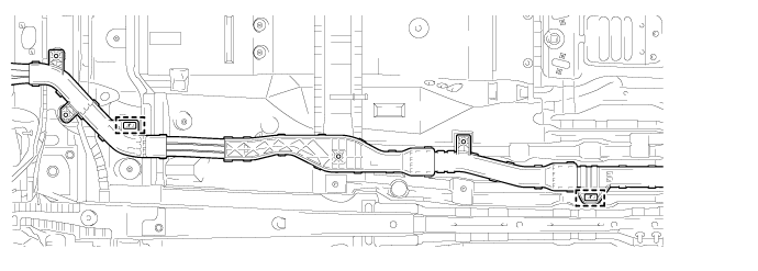
Install the No. 4 floor wire with 2 new clamps shown in the illustration.
FRAME WIRE > INSTALLATION |
| 1. INSTALL NO. 4 FLOOR WIRE |
Install the No. 4 floor wire with 2 new clamps shown in the illustration.
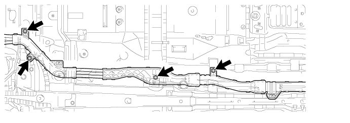
Install the 4 nuts shown in the illustration.
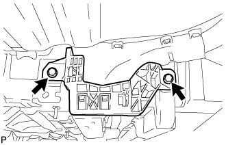 |
Install the 2 bolts shown in the illustration.
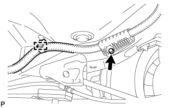 |
Connect the wire harness clamp and install the bolt shown in the illustration.
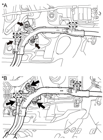 |
Install the 2 nuts shown in the illustration.
| *A | for LHD: |
| *B | for RHD: |
Connect the connector and 2 wire harness clamps.
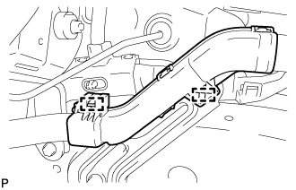 |
Connect the 2 wire harness clamps shown in the illustration.
Insert the No. 4 floor wire into the floor panel hole.
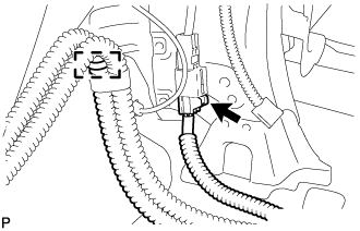 |
Connect the connector and wire harness clamp.
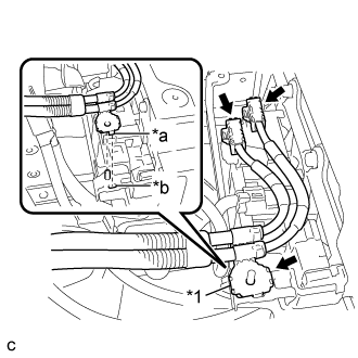 |
Connect the 2 connectors.
| *1 | Shielded Wire Ground |
| *a | Claw |
| *b | Hole |
Connect the shielded wire ground.
| 2. INSTALL NO. 4 HYBRID BATTERY SHIELD PANEL |
Install the No. 4 hybrid battery shield panel to the HV battery with the bolt and 2 nuts.
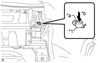 |
Install the battery cover lock striker, then push the button to lock it.
| *1 | Battery Cover Lock Striker |
| *a | Button |
| *b | Push |
| 3. INSTALL NO. 2 FRONT FLOOR FOOTREST COVER RH |
Install the No. 2 front floor footrest cover RH with the 6 clips.
| 4. INSTALL ROOM PARTITION BOARD LH |
Engage the 5 claws and clip to install the room partition board LH.
Install the clip.
| 5. INSTALL REAR SIDE SEATBACK ASSEMBLY RH |
Place the rear side seatback assembly RH in the cabin.
Engage the hook to install the rear side seatback assembly RH with the bolt.
Connect the rear seat outer belt to the rear seat shoulder belt guide RH.
| 6. INSTALL REAR SEATBACK ASSEMBLY RH |
Lift the rear seatback assembly RH.
| 7. INSTALL FUEL TANK ASSEMBLY |
| 8. INSTALL ENGINE ASSEMBLY WITH TRANSAXLE |