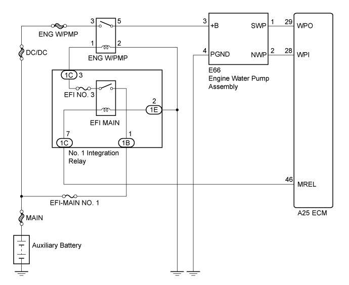
DTC P261B Engine Coolant Pump "B" Control Malfunction |
DTC P261C Engine Coolant Pump "B" Control Circuit Low |
DTC P261D Engine Coolant Pump "B" Control Circuit High |
| DTC No. | DTC Detection Condition | Trouble Area |
| P261B | Engine water pump assembly speed is less than 900 rpm while the engine water pump assembly is operating (1 trip detection logic). |
|
| P261C | Engine water pump assembly output voltage is less than specified value while the engine water pump assembly is operating (1 trip detection logic). |
|
| P261D | Engine water pump assembly output voltage is higher than specified value while the engine water pump assembly is operating (1 trip detection logic). |
|
| Required Sensors/Components | Engine water pump assembly |
| Frequency of Operation | Continuous |
| Tester Display | Description |
| NORMAL |
|
| ABNORMAL |
|
| INCOMPLETE |
|
| N/A |
|
| 1.PERFORM ACTIVE TEST USING INTELLIGENT TESTER (ACTIVATE THE ELECTRIC WATER PUMP) |
Connect the intelligent tester to the DLC3.
Turn the power switch on (IG).
Turn the tester on.
Enter the following menus: Powertrain / Engine and ECT / Active Test / Activate the Electric Water Pump.
Touch the engine water pump and check that the pump assembly is operating (vibrating).
|
| ||||
| OK | |
 |
| 2.CHECK HARNESS AND CONNECTOR (ENGINE WATER PUMP ASSEMBLY - ECM) |
Disconnect the engine water pump assembly connector.
Disconnect the ECM connector.
Measure the resistance according to the value(s) in the table below.
| Tester Connection | Condition | Specified Condition |
| E66-2 (NWP) - A25-28 (WPI) | Always | Below 1 Ω |
| E66-1 (SWP) - A25-29 (WPO) | Always | Below 1 Ω |
| E66-2 (NWP) or A25-28 (WPI) - Body ground | Always | 10 kΩ or higher |
| E66-1 (SWP) or A25-29 (WPO) - Body ground | Always | 10 kΩ or higher |
|
| ||||
| OK | |
|
| 3.CHECK TERMINAL VOLTAGE (WPI VOLTAGE) |
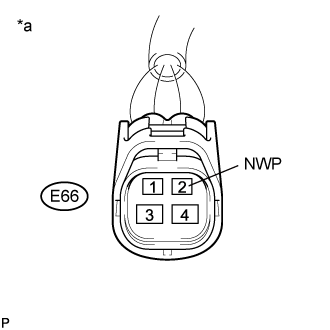 |
Disconnect the engine water pump assembly connector.
Turn the power switch on (IG).
Measure the voltage according to the value(s) in the table below.
| Tester Connection | Condition | Specified Condition |
| E66-2 (NWP) - Body ground | Power switch on (IG) | 11 to 14 V |
| *a | Front view of wire harness connector (to Engine Water Pump Assembly) |
|
| ||||
| OK | ||
 | ||
| ||
| 4.CHECK TERMINAL VOLTAGE (POWER SOURCE OF ENGINE WATER PUMP ASSEMBLY) |
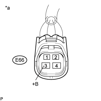 |
Disconnect the engine water pump assembly connector.
Turn the power switch on (IG).
Measure the voltage according to the value(s) in the table below.
| Tester Connection | Condition | Specified Condition |
| E66-3 (+B) - Body ground | Power switch on (IG) | 11 to 14 V |
| *a | Front view of wire harness connector (to Engine Water Pump Assembly) |
|
| ||||
| OK | |
|
| 5.CHECK HARNESS AND CONNECTOR (ENGINE WATER PUMP ASSEMBLY - BODY GROUND) |
Disconnect the engine water pump assembly connector.
Measure the resistance according to the value(s) in the table below.
| Tester Connection | Condition | Specified Condition |
| E66-4 (PGND) - Body ground | Always | Below 1 Ω |
|
| ||||
| OK | |
|
| 6.CHECK HARNESS AND CONNECTOR (ENGINE WATER PUMP ASSEMBLY - ECM) |
Disconnect the engine water pump assembly connector.
Disconnect the ECM connector.
Measure the resistance according to the value(s) in the table below.
| Tester Connection | Condition | Specified Condition |
| E66-2 (NWP) - A25-28 (WPI) | Always | Below 1 Ω |
| E66-1 (SWP) - A25-29 (WPO) | Always | Below 1 Ω |
| E66-2 (NWP) or A25-28 (WPI) - Body ground | Always | 10 kΩ or higher |
| E66-1 (SWP) or A25-29 (WPO) - Body ground | Always | 10 kΩ or higher |
|
| ||||
| OK | |
|
| 7.REPLACE ENGINE WATER PUMP ASSEMBLY |
Replace the engine water pump assembly (Click here).
| NEXT | |
|
| 8.CHECK WHETHER DTC OUTPUT RECURS (DTC P261B, P261C OR P261D) |
Connect the intelligent tester to the DLC3.
Turn the power switch on (IG).
Turn the tester on.
Clear the DTCs (Click here)
Turn the power switch off and wait for at least 30 seconds.
Turn the power switch on (IG).
Turn the tester on.
Drive the vehicle in accordance with the driving pattern described in the Confirmation Driving Pattern.
Enter the following menus: Powertrain / Engine and ECT / DTC.
Read the DTCs.
| Result | Proceed to |
| DTC P261B, P261C or P261D is output | A |
| DTC is not output | B |
|
| ||||
| A | ||
| ||
| ||
| 9.INSPECT RELAY (ENG W/PMP RELAY) |
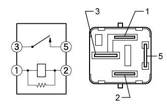 |
Remove the ENG W/PMP relay from the engine room relay block and junction block assembly.
Measure the resistance according to the value(s) in the table below.
| Tester Connection | Condition | Specified Condition |
| 3 - 5 | No auxiliary battery voltage applied between terminals 1 and 2 | 10 kΩ or higher |
| 3 - 5 | Auxiliary battery voltage applied between terminals 1 and 2 | Below 1 Ω |
|
| ||||
| OK | |
|
| 10.CHECK HARNESS AND CONNECTOR (ENG W/PMP RELAY - ENGINE WATER PUMP ASSEMBLY) |
Remove the ENG W/PMP relay from the engine room relay block and junction block assembly.
Disconnect the engine water pump assembly connector.
Measure the resistance according to the value(s) in the table below.
| Tester Connection | Condition | Specified Condition |
| ENG W/PMP relay terminal 5 - E66-3 (+B) | Always | Below 1 Ω |
| ENG W/PMP relay terminal 5 or E66-3 (+B) - Body ground | Always | 10 kΩ or higher |
|
| ||||
| OK | |
|
| 11.CHECK TERMINAL VOLTAGE (POWER SOURCE OF ENG W/PMP RELAY) |
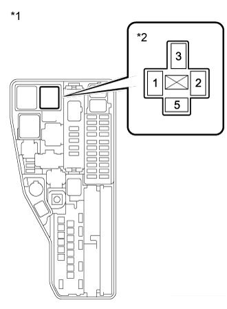 |
Remove the ENG W/PMP relay from the engine room relay block and junction block assembly.
Measure the voltage according to the value(s) in the table below.
| Tester Connection | Condition | Specified Condition |
| ENG W/PMP relay terminal 3 - Body ground | Always | 11 to 14 V |
| *1 | Engine Room Relay Block and Junction Block Assembly |
| *2 | ENG W/PMP Relay |
|
| ||||
| OK | |
|
| 12.CHECK HARNESS AND CONNECTOR (ENG W/PMP RELAY - BODY GROUND) |
Remove the ENG W/PMP relay from the engine room relay block and junction block assembly.
Measure the resistance according to the value(s) in the table below.
| Tester Connection | Condition | Specified Condition |
| ENG W/PMP relay terminal 2 - Body ground | Always | Below 1 Ω |
|
| ||||
| OK | ||
| ||
| ||

