METER / GAUGE SYSTEM > Engine Coolant Temperature Receiver Gauge Malfunction |
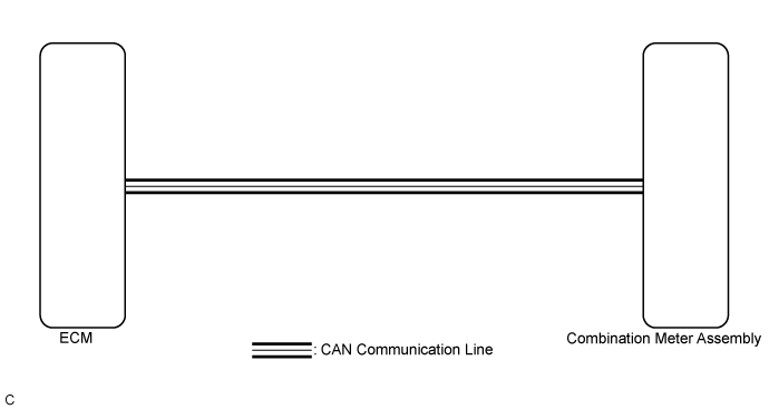
| 1.CHECK CAN COMMUNICATION SYSTEM |
Check if a CAN communication DTC is output (Click here).
| Result | Proceed to |
| CAN communication DTC is not output. | A |
| CAN communication DTC is output. | B |
|
| ||||
| A | |
 |
| 2.PERFORM ACTIVE TEST USING GTS (WATER TEMPERATURE METER OPERATION) |
Connect the GTS to the DLC3.
Turn the ignition switch to ON.
Turn the GTS on.
Enter the following menus: Body Electrical / Combination Meter / Active Test.
Perform the Active Test according to the display on the GTS.
| Tester Display | Test Part | Control Range | Diagnostic Note |
| Water Temperature Meter Operation | Engine coolant temperature receiver gauge | OFF, LOW, NORMAL, HIGH | - |
|
| ||||
| OK | |
|
| 3.CHECK SFI SYSTEM |
Check if the SFI system output the DTC (Click here for 2AR-FE, Click here for 2GR-FE, Click here for 6AR-FSE).
| Result | Proceed to |
| SFI system DTCs are not output. | A |
| SFI system DTCs are output (for 2AR-FE). | B |
| SFI system DTCs are output (for 2GR-FE). | C |
| SFI system DTCs are output (for 6AR-FSE). | D |
|
| ||||
|
| ||||
|
| ||||
| A | |
|
| 4.READ VALUE USING GTS (COOLANT TEMP, COOLANT TEMPERATURE) |
Connect the GTS to the DLC3.
Turn the ignition switch to ON.
Turn the GTS on.
Enter the following menus:
for Engine and ECT: Powertrain / Engine and ECT / Data List.
for Combination Meter: Body Electrical / Combination Meter / Data List.
Read the Data List according to the display on the GTS.
| Tester Display | Measurement Item/Range | Normal Condition | Stored as Freeze Frame Data |
| Coolant Temp | Engine coolant temperature/Min.: -40°C (-40°F), Max.: 140°C (284°F) | 75 to 100°C (167 to 212°F): After warming up | Yes |
| Diagnostic Note: This is the engine coolant temperature.
| |||
| Tester Display | Measurement Item/Range | Normal Condition | Diagnostic Note |
| Coolant Temperature | Engine coolant temperature/Min.: 0°C (32°F), Max.: 127.5°C (261.5°F) | 75 to 100°C (167 to 212°F): After warming up engine | - |
| Result | Proceed to |
| The data list values of the ECUs match. | A |
| The data list values of the ECUs do not match (for 2AR-FE). | B |
| The data list values of the ECUs do not match (for 2GR-FE). | C |
| The data list values of the ECUs do not match (for 6AR-FSE). | D |
|
| ||||
|
| ||||
|
| ||||
| A | ||
 | ||
| ||
