 |
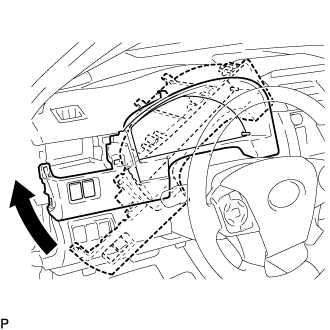
Temporarily install the instrument cluster finish panel assembly as shown in the illustration.
CLEARANCE SONAR MAIN SWITCH > INSTALLATION |
| 1. INSTALL BACK SONAR OR CLEARANCE SONAR SWITCH ASSEMBLY (for LHD) |
Engage the 2 claws to install the back sonar or clearance sonar switch assembly.
| 2. INSTALL BACK SONAR OR CLEARANCE SONAR SWITCH ASSEMBLY (for RHD) |
Engage the 2 claws to install the back sonar or clearance sonar switch assembly.
| 3. INSTALL INSTRUMENT CLUSTER FINISH PANEL ASSEMBLY |
|
Temporarily install the instrument cluster finish panel assembly as shown in the illustration.
Connect each connector.
for LHD:
Engage the 3 claws, 7 clips and 4 guides.
for RHD:
Engage the 4 claws, 5 clips and 4 guides.
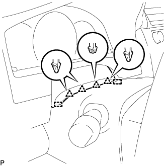 |
Engage the 4 clips and 2 guides to install the instrument cluster finish panel assembly.
| 4. INSTALL NO. 1 INSTRUMENT PANEL REGISTER ASSEMBLY |
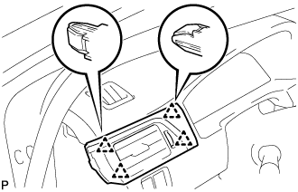 |
Engage the 4 clips to install the No. 1 instrument panel register assembly.
| 5. INSTALL UPPER INSTRUMENT PANEL FINISH PANEL (for RHD) |
w/ Smart Entry and Start System:
Connect the connector.
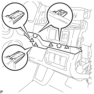 |
Engage the 2 claws and 4 clips to install the upper instrument panel finish panel.
| 6. INSTALL INSTRUMENT SIDE PANEL |
Engage the 3 guides.
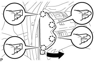 |
Engage the 4 claws to install the instrument side panel LH as shown in the illustration.
| 7. INSTALL FRONT DOOR OPENING TRIM WEATHERSTRIP |
| 8. CONNECT CABLE TO NEGATIVE BATTERY TERMINAL (for RHD with Smart Entry and Start System) |
| 9. CUSTOMIZE POWER TILT AND POWER TELESCOPIC STEERING COLUMN SYSTEM (for Power Tilt and Power Telescopic Steering Column) |