 |
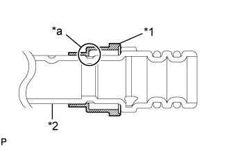
Install a new piping clamp to the No. 1 cooler refrigerant suction hose.
| *1 | Piping Clamp |
| *2 | No. 1 Cooler Refrigerant Suction Hose |
| *a | Groove |
- NOTICE:
- Securely engage the inside step of the piping clamp in the suction hose groove.
REFRIGERANT LINE (for TMC, TMMR Made) > INSTALLATION |
| 1. INSTALL PIPING CLAMP (for 2AR-FE, 6AR-FSE) |
Remove the vinyl tape from the open ends of the suction pipe sub-assembly and No. 1 cooler refrigerant suction hose.
|
Install a new piping clamp to the No. 1 cooler refrigerant suction hose.
| *1 | Piping Clamp |
| *2 | No. 1 Cooler Refrigerant Suction Hose |
| *a | Groove |
Thoroughly coat 2 new O-rings and the contact surface of the No. 1 cooler refrigerant suction hose with compressor oil (ND-OIL 8).
Install the 2 O-rings to the No. 1 cooler refrigerant suction hose.
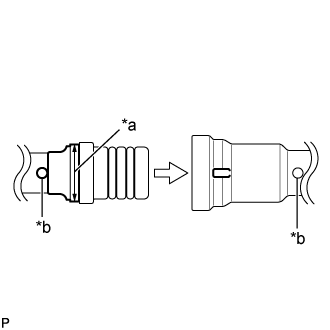 |
Engage the suction pipe sub-assembly and No. 1 cooler refrigerant suction hose by matching the alignment marks.
| *a | Large Diameter Section of Piping Clamp |
| *b | Alignment Mark |
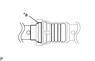 |
Securely insert the piping clamp to the point where the large diameter section of the piping clamp is covered by the suction pipe sub-assembly.
| *a | Large Diameter Section of Piping Clamp |
| 2. INSTALL PIPING CLAMP (for 2GR-FE) |
Remove the vinyl tape from the open ends of the suction pipe sub-assembly and No. 1 cooler refrigerant suction hose.
|
Install a new piping clamp to the No. 1 cooler refrigerant suction hose.
| *1 | Piping Clamp |
| *2 | No. 1 Cooler Refrigerant Suction Hose |
| *a | Groove |
Thoroughly coat 2 new O-rings and the contact surface of the No. 1 cooler refrigerant suction hose with compressor oil (ND-OIL 8).
Install the 2 O-rings to the No. 1 cooler refrigerant suction hose.
|
Engage the suction pipe sub-assembly and No. 1 cooler refrigerant suction hose by matching the alignment marks.
| *a | Large Diameter Section of Piping Clamp |
| *b | Alignment Mark |
|
Securely insert the piping clamp to the point where the large diameter section of the piping clamp is covered by the suction pipe sub-assembly.
| *a | Large Diameter Section of Piping Clamp |
| 3. CHARGE AIR CONDITIONING SYSTEM WITH REFRIGERANT |
Perform vacuum purging using a vacuum pump or appropriate equipment.
Charge the air conditioning system with refrigerant.
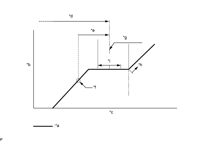
| *a | Sub-cool System | *b | High Pressure |
| *c | Refrigerant Amount | *d | Standard charge amount |
| *e | Charge additional 100 g (3.5 oz) | *f | Point where bubbles disappear |
| *g | Mean value in proper range | *h | Overcharged |
| *i | +/-50 g (+/-1.76 oz) | - | - |
| 4. WARM UP ENGINE |
Keep the A/C switch on for at least 2 minutes to warm up the compressor.
| 5. INSPECT FOR REFRIGERANT LEAK |
After recharging the air conditioning system with refrigerant, check for refrigerant leaks using a halogen leak detector.
Carry out the test under the following conditions:
Remove the front outer cowl top panel sub-assembly .
Remove the radiator side deflector RH .
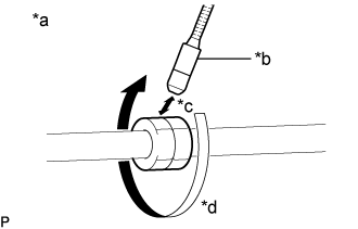 |
How to check for refrigerant leaks in pipe joints:
| *a | Check for leaks |
| *b | Halogen Leak Detector Sensor |
| *c | Distance between Sensor and Joint to be Checked: 10 mm or less |
| *d | Halogen Leak Detector Sensor Moving Speed: 25 to 50 mm/sec. |
Using a halogen leak detector, check for refrigerant leaks at the pipe joints shown in the illustration.
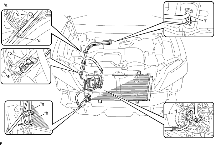
| *a | Area to be Checked | *b | Service Valve (High) |
| *c | Service Valve (Low) | *d | Pipe Joint |
| *e | Air Conditioner Pressure Sensor Joint | *f | Cooler Expansion Valve Joint |
| *g | Condenser Joint (Inlet) | *h | Condenser Joint (Outlet) |
| *i | Compressor Joint (Inlet) | *j | Compressor Joint (Outlet) |
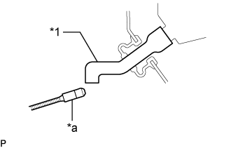 |
Bring the halogen leak detector sensor close to the drain cooler hose with the detector turned off, and then turn the detector on.
| *1 | Drain Cooler Hose |
| *a | Halogen Leak Detector |
Remove the blower motor with fan sub-assembly (Click here).
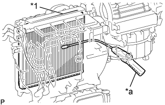 |
Insert the halogen leak detector sensor into the air conditioning unit assembly, bring the sensor close to the No. 1 cooler evaporator sub-assembly and check for refrigerant leaks.
| *1 | No. 1 Cooler Evaporator Sub-assembly |
| *a | Halogen Leak Detector |
Install the blower motor with fan sub-assembly (Click here).
Install the radiator side deflector RH .
Install the front bumper assembly (Click here).
Install the front outer cowl top panel sub-assembly (Click here for LHD or Click here for RHD).