| NG |  |
| Go to step 5 |
ENGINE IMMOBILISER SYSTEM (w/o Smart Entry and Start System) > Key Cannot be Registered |
| 1.CHECK REGISTRATION MODE |
Check that the system enters registration mode.
|
| ||||
| OK | |
 |
| 2.CHECK SECURITY INDICATOR LIGHT OPERATION |
In registration mode, insert the door control transmitter assembly into the ignition key cylinder and check the security indicator light.
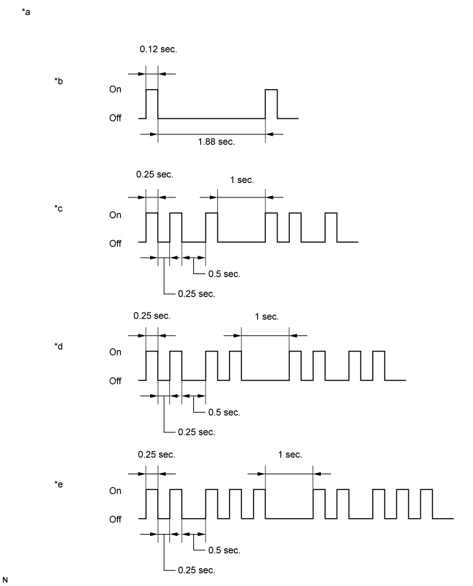
| *a | Security Indicator Light | *b | Normal (Immobiliser system is operating normally) |
| *c | Code 2-1 | *d | Code 2-2 |
| *e | Code 2-3 | - | - |
| Result | Proceed to |
| Code 2-2 is output | A |
| Code 2-1 or Code 2-3 is output | B |
|
| ||||
| A | ||
 | ||
| ||
| 3.READ VALUE USING INTELLIGENT TESTER (TRANSPONDER S-CODE, TRANSPONDER M-CODE) |
Connect the intelligent tester to the DLC3.
Turn the ignition switch to ON.
Turn the intelligent tester on.
Enter the following menus: Body / Immobiliser / Data List.
Read the Data List according to the display on the intelligent tester.
| Tester Display | Measurement Item/Range | Normal Condition | Diagnostic Note |
| Transponder S-code | Number of registered sub key/min. 0, max. 15 | Number of registered sub keys displayed | - |
| Transponder M-code | Number of registered master key/min. 0, max. 15 | Number of registered master keys displayed | - |
| Result | Proceed to |
| Values are other than above | A |
| 5 is displayed for "Transponder M-code" and 0 is displayed for "Transponder S-code" | B |
| 0 is displayed for "Transponder M-code" and 3 is displayed for "Transponder S-code" | C |
| 5 is displayed for "Transponder M-code" and 3 is displayed for "Transponder S-code" | D |
|
| ||||
|
| ||||
|
| ||||
| A | |
|
| 4.KEY REGISTRATION |
Refer to the table below to determine if additional door control transmitter assemblies can be registered.
| Number of Door control transmitter assemblies Registered (Master and Sub | Proceed to |
| 0 | New key ID code registration |
| 1 to 7 | Additional key ID code registration |
Check if an additional door control transmitter assembly can be registered.
|
| ||||
| OK | ||
| ||
| ||
| 5.INSPECT UNLOCK WARNING SWITCH ASSEMBLY |
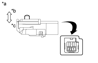 |
Remove the unlock warning switch assembly (Click here).
Measure the resistance according to the value(s) in the table below.
| Tester Connection | Condition | Specified Condition |
| 1 - 2 | Pushed (Key set) | Below 1 Ω |
| 1 - 2 | Free (Key removed) | 10 kΩ or higher |
| *a | Component without harness connected (Unlock Warning Switch Assembly) |
| *b | Free |
| *c | Pushed |
|
| ||||
| OK | |
|
| 6.CHECK HARNESS AND CONNECTOR (TRANSPONDER KEY ECU ASSEMBLY - UNLOCK WARNING SWITCH ASSEMBLY - BODY GROUND) |
Disconnect the I19 transponder key ECU assembly connector.
Measure the resistance according to the value(s) in the table below.
| Tester Connection | Condition | Specified Condition |
| I19-3 (KSW) - I33-1 (UN+) | Always | Below 1 Ω |
| I19-3 (KSW) or I33-1 (UN+) - Body ground | Always | 10 kΩ or higher |
| I33-2 (UN-) - Body ground | Always | Below 1 Ω |
|
| ||||
| OK | ||
| ||
| ||
