 |
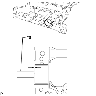
Using a vernier caliper, measure the distance between the camshaft housing sub-assembly edge and the No. 2 camshaft bearing edge.
| *a | Vernier Caliper |
- Standard Distance:
- 1.15 to 1.85 mm (0.0453 to 0.0728 in.)
CAMSHAFT > INSTALLATION |
| 1. INSTALL NO. 2 CAMSHAFT BEARING |
Clean the No. 2 camshaft bearing.
Install the No. 2 camshaft bearing to the camshaft housing sub-assembly.
|
Using a vernier caliper, measure the distance between the camshaft housing sub-assembly edge and the No. 2 camshaft bearing edge.
| *a | Vernier Caliper |
| 2. INSTALL NO. 1 CAMSHAFT BEARING |
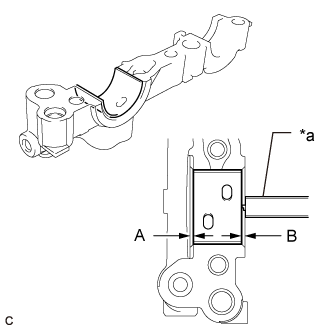 |
Clean the No. 1 camshaft bearing.
| *a | Vernier Caliper |
Install the No. 1 camshaft bearing to the No. 1 camshaft bearing cap.
Using a vernier caliper, measure the distance between the No. 1 camshaft bearing cap edge and the No. 1 camshaft bearing edge.
| 3. INSTALL OIL CONTROL VALVE FILTER |
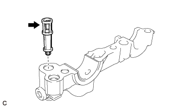 |
Install the oil control valve filter to the No. 1 camshaft bearing cap.
| 4. INSTALL CAMSHAFT TIMING EXHAUST GEAR ASSEMBLY |
Secure the No. 2 camshaft in a vise by clamping the hexagonal part between aluminum plates.
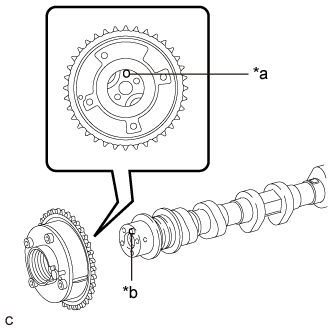 |
Align and fit the knock pin of the No. 2 camshaft with the knock pin hole of the camshaft timing exhaust gear assembly.
| *a | Knock Pin Hole |
| *b | Knock Pin |
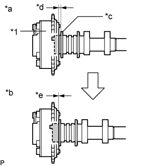 |
Check that there is no gap between the camshaft timing exhaust gear assembly and No. 2 camshaft flange.
| *1 | Camshaft Timing Exhaust Gear Assembly |
| *a | Incorrect |
| *b | Correct |
| *c | No. 2 Camshaft Flange |
| *d | Gap |
| *e | No Gap |
Secure the camshaft timing exhaust gear assembly with the bolt.
| 5. SET NO. 1 CYLINDER TO TDC/COMPRESSION |
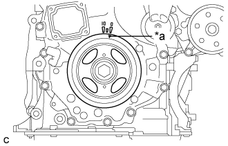 |
Turn the crankshaft pulley until its timing notch (groove) and the timing mark "0" of the timing chain cover sub-assembly are aligned.
| *a | Timing Notch (Groove) |
| 6. INSTALL NO. 2 CAMSHAFT |
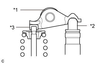 |
Make sure that the No. 1 valve rocker arm sub-assemblies are installed as shown in the illustration.
| *1 | No. 1 Valve Rocker Arm Sub-assembly |
| *2 | Valve Lash Adjuster Assembly |
| *3 | Valve Stem Cap |
Clean the camshaft journals.
Apply a light coat of engine oil to the camshaft journals, camshaft housing sub-assembly and camshaft bearing caps.
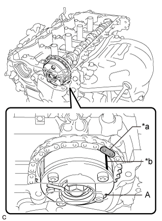 |
Hold up the chain sub-assembly, align the timing mark and paint mark, and install the No. 2 camshaft to the camshaft housing sub-assembly.
| *a | Paint Mark |
| *b | Timing Mark |
| 7. INSTALL CAMSHAFT TIMING GEAR ASSEMBLY |
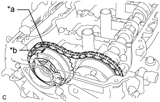 |
Align the paint mark of the chain sub-assembly and the timing mark of the camshaft timing gear assembly. Then install the camshaft timing gear assembly.
| *a | Paint Mark |
| *b | Timing Mark |
| 8. INSTALL CAMSHAFT |
|
Make sure that the No. 1 valve rocker arm sub-assemblies are installed as shown in the illustration.
| *1 | No. 1 Valve Rocker Arm Sub-assembly |
| *2 | Valve Lash Adjuster Assembly |
| *3 | Valve Stem Cap |
Clean the camshaft journals.
Apply a light coat of engine oil to the camshaft journals and camshaft housing sub-assembly.
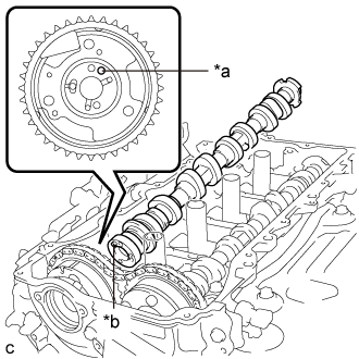 |
Align and fit the knock pin of the camshaft with the knock pin hole of the camshaft timing gear assembly.
| *a | Knock Pin Hole |
| *b | Knock Pin |
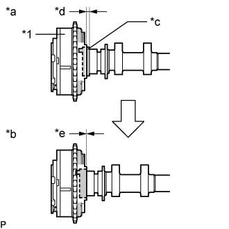 |
Check that there is no gap between the camshaft timing gear assembly and portion (A) of the camshaft shown in the illustration.
| *1 | Camshaft Timing Gear Assembly |
| *a | Incorrect |
| *b | Correct |
| *c | Portion (A) of Camshaft |
| *d | Gap |
| *e | No Gap |
| 9. TEMPORARILY INSTALL CAMSHAFT TIMING GEAR BOLT |
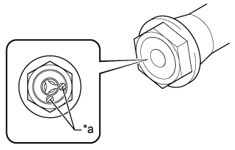 |
| Item | Identification Mark Stamp |
| Type A | A |
| Type B | D |
| *a | Identification Mark Stamp |
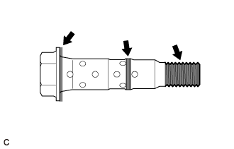 |
Apply engine oil to the areas of the camshaft timing gear bolt shown in the illustration.
Temporarily install the camshaft timing gear bolt.
| 10. INSTALL CAMSHAFT BEARING CAP |
Place the No. 1 camshaft bearing cap, No. 2 camshaft bearing cap, No. 3 camshaft bearing cap and No. 4 camshaft bearing cap in their correct positions.
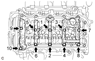 |
Uniformly tighten the 10 bolts in several steps in the order shown in the illustration.
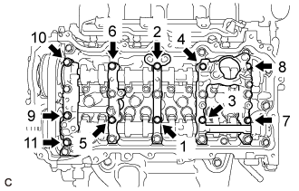 |
Uniformly tighten the 11 bolts in several steps in the order shown in the illustration.
Check the torque of each bolt again.
| 11. TIGHTEN CAMSHAFT TIMING GEAR BOLT |
|
| Item | Identification Mark Stamp |
| Type A | A |
| Type B | D |
| *a | Identification Mark Stamp |
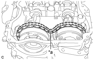 |
Check that there is some slack in the chain sub-assembly as shown in the illustration.
| *a | Slack |
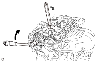 |
Use a wrench to hold the hexagonal portion of the camshaft.
| *a | Hold |
 | Turn |
Tighten the camshaft timing gear bolt.
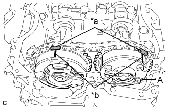 |
Check that the paint marks of the chain sub-assembly are aligned with the timing mark of the camshaft timing gear assembly and the camshaft timing exhaust gear assembly.
| *a | Paint Mark |
| *b | Timing Mark |
| 12. ADD ENGINE OIL |
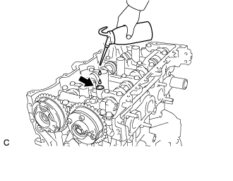 |
Add 50 cc (3.1 cu. in.) of engine oil into the oil hole shown in the illustration.
| 13. INSTALL TIMING CHAIN GUIDE |
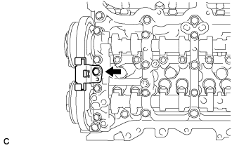 |
Install the timing chain guide with the bolt.
| 14. INSTALL NO. 1 CHAIN TENSIONER ASSEMBLY |
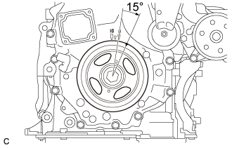 |
Turn the crankshaft pulley approximately 15° clockwise.
Install a new gasket and the No. 1 chain tensioner assembly with the 2 bolts.
Remove the pin from the stopper plate.
| 15. SET NO. 1 CYLINDER TO TDC/COMPRESSION |
Turn the crankshaft pulley until its timing notch (groove) and the timing mark "0" of the timing chain cover sub-assembly are aligned.
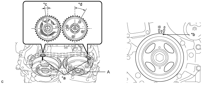
| *a | Timing Mark | *b | Timing Notch (Groove) |
| *c | Approximately 7° | *d | Approximately 32° |
Check that both timing marks on the camshaft timing gear assembly and camshaft timing exhaust gear assembly are facing upward as shown in the illustration. If not, turn the crankshaft 1 revolution (360°) to align the timing marks as shown in the illustration.
| 16. INSTALL TIMING CHAIN COVER PLATE |
Install a new gasket and the timing chain cover plate with the 4 bolts.
| 17. INSTALL CAMSHAFT TIMING OIL CONTROL SOLENOID ASSEMBLY |
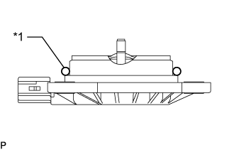 |
Apply engine oil to a new O-ring and install it to the camshaft timing oil control solenoid assembly as shown in the illustration.
| *1 | O-ring |
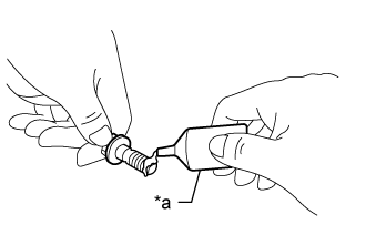 |
Apply adhesive to 2 or 3 threads of 2 new bolts.
| *a | Adhesive 1324 |
Install the camshaft timing oil control solenoid assembly to the timing chain cover sub-assembly with the 2 bolts.
Connect the camshaft timing oil control solenoid assembly connector.
| 18. INSTALL CYLINDER HEAD COVER SUB-ASSEMBLY |
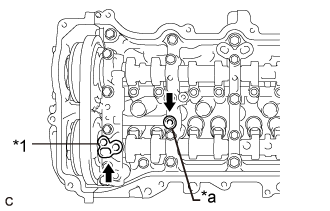 |
Apply a light coat of engine oil to a new camshaft bearing cap oil hole gasket and a new gasket.
| *1 | Camshaft Bearing Cap Oil Hole Gasket |
| *a | Gasket |
Install the camshaft bearing cap oil hole gasket to the No. 1 camshaft bearing cap.
Install the gasket to the No. 2 camshaft bearing cap.
Install a new cylinder head cover gasket to the cylinder head cover sub-assembly.
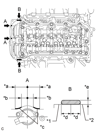 |
Apply seal packing as shown in the illustration.
| *1 | Timing Chain Cover Sub-assembly |
| *2 | Camshaft Housing Sub-assembly |
| *a | 45 mm (1.77 in.) |
| *b | 24 mm (0.945 in.) |
| *c | Seal Packing Diameter: 3.0 mm (0.118 in.) |
| *d | Application Width 5.0 mm (0.197 in.) |
| *e | Seal Packing Diameter: 3.0 to 6.0 mm (0.118 to 0.236 in.) |
| Seal Packing |
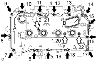 |
Align the cylinder head cover sub-assembly with the pin (A). Then align the cylinder head cover sub-assembly with the pin (B) and install the cylinder head cover sub-assembly.
| Bolt |
 | Bolt with Seal Washer |
Install 3 new seal washers and the 17 bolts, and then tighten the bolts in the order shown in the illustration.
| 19. CONNECT NO. 2 VENTILATION HOSE |
Connect the No. 2 ventilation hose to the PCV valve (ventilation valve sub-assembly) and slide the clip to secure it.
| 20. INSTALL IGNITION COIL ASSEMBLY |
Install the 4 ignition coil assemblies to the cylinder head cover sub-assembly with the 4 bolts.
Connect the 4 ignition coil assembly connectors.
| 21. INSTALL ENGINE MOVING CONTROL ROD BRACKET |
When replacing the engine moving control rod.
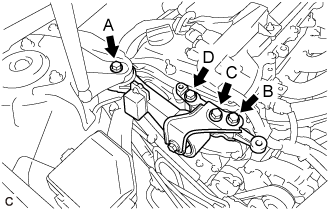 |
Install the engine moving control rod bracket with engine moving control rod with the 4 bolts.
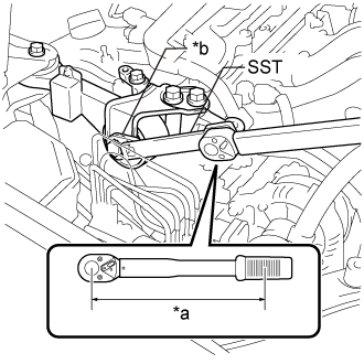 |
Using SST and a union nut wrench (14 mm), tighten the bolt.
| *a | Torque Wrench Fulcrum Length |
| *b | Union Nut Wrench |
When not replacing the engine moving control rod.
|
Install the engine moving control rod bracket with engine moving control rod with the 4 bolts.
| 22. INSTALL NO. 2 ENGINE MOUNTING STAY RH |
Install the No. 2 engine mounting stay RH with the 2 bolts.
| 23. INSTALL EARTH WIRE |
Install the earth wire with the 2 bolts.
| 24. INSTALL VACUUM PUMP ASSEMBLY |
| 25. INSTALL FUEL PUMP WITH SEAL SUB-ASSEMBLY (for High Pressure) |
| 26. CONNECT ENGINE WIRE |
Connect the engine wire to the engine assembly with the 4 nuts and 5 bolts.
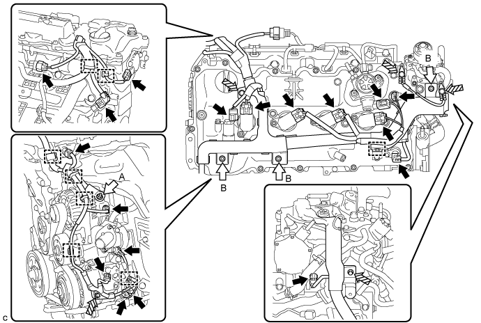
| Connector | | Nut |
 | Bolt | - | - |
Connect the 18 connectors and 8 clamps.
Engage the clamp to connect the heater inlet water hose.
| 27. INSTALL AIR CLEANER CASE SUB-ASSEMBLY |
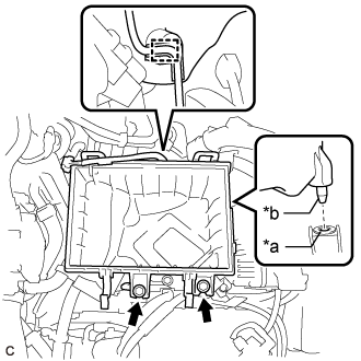 |
Insert the projection of the air cleaner case sub-assembly into the hole of the No. 1 air cleaner bracket as shown in the illustration.
| *a | Hole |
| *b | Projection |
Install the 2 bolts.
Connect the wire harness clamp.
| 28. INSTALL AIR CLEANER FILTER ELEMENT SUB-ASSEMBLY |
Install the air cleaner filter element sub-assembly to the air cleaner case sub-assembly.
| 29. INSTALL AIR CLEANER CAP WITH AIR CLEANER HOSE |
Connect the air cleaner cap with air cleaner hose to the throttle body with motor assembly.
Install the air cleaner cap with air cleaner hose with the 2 guides and 2 air cleaner cap clamps.
Tighten the hose clamp.
Connect the union to connector tube hose to the air cleaner hose sub-assembly.
Engage the wire harness clamp.
Connect the mass air flow meter sub-assembly connector.
Engage the ventilation hose clamp.
Connect the ventilation hose to the cylinder head cover sub-assembly and slide the clip to secure it.
| 30. INSTALL INLET AIR CLEANER ASSEMBLY |
Install the inlet air cleaner assembly with the 2 bolts.
| 31. INSTALL NO. 1 ENGINE COVER SUB-ASSEMBLY |
Engage the 3 grommets to install the No. 1 engine cover sub-assembly.
| 32. INSTALL COOL AIR INTAKE DUCT SEAL |
Install the cool air intake duct seal with the 9 clips.
| 33. CONNECT CABLE TO NEGATIVE BATTERY TERMINAL |
| 34. INSPECT FOR ENGINE OIL LEAK |
| 35. INSTALL FRONT FENDER APRON SEAL RH |
Install the front fender apron seal RH with the 2 bolts and clip.
| 36. INSTALL ENGINE UNDER COVER RH |
Install the engine under cover RH with the 3 screws and 3 clips.
| 37. INSTALL FRONT WHEEL OPENING EXTENSION PAD RH |
Install the front wheel opening extension pad LH with the 3 screws.
| 38. INSTALL FRONT WHEEL RH |
| 39. OPERATION CHECK |