A25A-FKS EMISSION CONTROL EGR VALVE INSTALLATION
CAUTION / NOTICE / HINT
- NOTICE:
-
This procedure includes the installation of small-head bolts. Refer to Small-Head Bolts of Basic Repair Hint to identify the small-head bolts.
-
Click hereGeneral>INTRODUCTION>REPAIR INSTRUCTION>PRECAUTION
PROCEDURE

 25620
1.INSTALL EGR VALVE ASSEMBLY
Using an 8 mm socket wrench, install the EGR valve assembly to the EGR valve bracket with the bolt.
- Torque:
- 10 N*m (102 kgf*cm, 7 ft.*lbf)
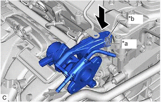
| *a | Pin |
| *b | Hole |
Align and fit the hole of the EGR valve bracket to the pin of the camshaft housing.
Using the 8 mm socket wrench, install the EGR valve assembly with the EGR valve bracket to the camshaft housing with the bolt.
- Torque:
- 10 N*m (102 kgf*cm, 7 ft.*lbf)
for EGR Valve Bracket Connection Type:
Using the 8 mm socket wrench, connect the fuel pipe sub-assembly to the EGR valve bracket with the bolt.
- Torque:
- 10 N*m (102 kgf*cm, 7 ft.*lbf)
Install the EGR cooler bracket to the EGR valve bracket and water outlet with the 2 bolts.
- Torque:
- 24 N*m (245 kgf*cm, 18 ft.*lbf)
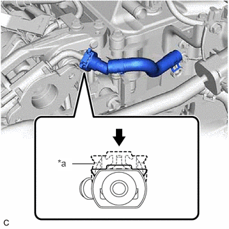
| *a | Retainer |

|
Push in |
w/ Water Hose Connector:
Align the water hose connector with the EGR valve assembly, push the No. 4 water by-pass hose onto the EGR valve assembly, then push in the retainer to secure the connection.
- NOTICE:
-
Confirm that the retainer makes a "click" sound when pushed.
Check that the EGR valve assembly and No. 4 water by-pass hose are securely connected by pulling on them.
w/o Water Hose Connector:
Install the No. 4 water by-pass hose to the EGR valve assembly and slide the clip to secure it.
Connect the No. 8 water by-pass hose to the EGR valve assembly and slide the clip to secure it.
25601
2.INSTALL NO. 1 EGR PIPE SUB-ASSEMBLY
Install a new EGR inlet gasket to the intake manifold.
Install a new EGR valve adapter gasket to the No. 1 EGR pipe sub-assembly.
Using an 8 mm socket wrench, install the No. 1 EGR pipe sub-assembly to the intake manifold and EGR valve assembly with the 4 bolts.
- Torque:
- 10 N*m (102 kgf*cm, 7 ft.*lbf)
3.CONNECT ENGINE WIRE
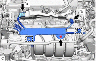
| *a | No. 5 Engine Wire Connector |
| *b | EGR Valve Assembly Connector |
Engage the 2 wire harness clamps to connect the engine wire.
Install the bolt.
- Torque:
- 10 N*m (102 kgf*cm, 7 ft.*lbf)
Connect the EGR valve assembly connector.
Connect the No. 5 engine wire connector.
25680
4.INSTALL EGR COOLER ASSEMBLY
5.INSTALL AIR CLEANER CAP WITH AIR CLEANER HOSE
12601B
6.INSTALL NO. 1 ENGINE COVER SUB-ASSEMBLY
7.ADD ENGINE COOLANT
8.INSPECT FOR COOLANT LEAK
9.INSPECT FOR EXHAUST GAS LEAK