2GR-FKS BATTERY / CHARGING GENERATOR INSTALLATION
PROCEDURE

 27020
1.INSTALL GENERATOR ASSEMBLY
Install the generator assembly with the 2 bolts.
- Torque:
- 43 N*m (438 kgf*cm, 32 ft.*lbf)
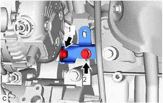
Install the generator assembly bracket with the 2 bolts in the order shown in the illustration.
- Torque:
- 20 N*m (204 kgf*cm, 15 ft.*lbf)
Install the wire harness clamp bracket with the 2 bolts.
- Torque:
- 10 N*m (102 kgf*cm, 7 ft.*lbf)
Engage the 3 wire harness clamps.
Connect the camshaft timing oil control solenoid assembly connector.
Connect the compressor assembly with magnetic clutch connector.
Connect the generator assembly connector.
Connect the wire harness to terminal B with the nut.
- Torque:
- 9.8 N*m (100 kgf*cm, 87 in.*lbf)
Close the terminal cap.
16361A
2.INSTALL V-RIBBED BELT
11209
3.INSTALL V-BANK COVER SUB-ASSEMBLY
16400
4.INSTALL RADIATOR ASSEMBLY
5.CONNECT CABLE TO NEGATIVE BATTERY TERMINAL
- NOTICE:
-
When disconnecting the cable, some systems need to be initialized after the cable is reconnected.
-
Click hereGeneral>INTRODUCTION>REPAIR INSTRUCTION>INITIALIZATION