A25A-FKS ENGINE CONTROL SFI SYSTEM(w/o Canister Pump Module) P052024 Engine Oil Pressure Sensor/Switch "A" Signal Stuck High P05202A Engine Oil Pressure Sensor/Switch "A" Signal Stuck in Range
DESCRIPTION
Refer to DTC P052012.
Click hereEngine / Hybrid System>A25A-FKS (ENGINE CONTROL)>SFI SYSTEM (w/o Canister Pump Module)>P052012
| DTC No. | Detection Item | DTC Detection Condition | Trouble Area | MIL | Memory | Note |
|---|---|---|---|---|---|---|
| P052024 | Engine Oil Pressure Sensor/Switch "A" Signal Stuck High | The oil pressure sensor output voltage is higher than the threshold value (1 trip detection logic). | ·
Open or short in oil pressure sensor (oil pressure sender gauge assembly) circuit ·
Oil pressure sensor (oil pressure sender gauge assembly) ·
ECM |
Comes on | DTC stored | SAE Code: P0521 |
| P05202A | Engine Oil Pressure Sensor/Switch "A" Signal Stuck in Range | The oil pressure sensor output voltage is the same value for a certain period of time (1 trip detection logic). | ·
Open or short in oil pressure sensor (oil pressure sender gauge assembly) circuit ·
Oil pressure sensor (oil pressure sender gauge assembly) ·
ECM |
Comes on | DTC stored | SAE Code: P0521 |
| DTC No. | Data List |
|---|---|
| P052024 | ·
Engine Oil Temperature Sensor ·
Engine Oil Pressure |
| P05202A |
MONITOR DESCRIPTION
The ECM calculates the engine oil pressure based on the output voltage of the oil pressure sensor. If any of the following are detected, the ECM will illuminate the MIL and store a DTC.
The oil pressure sensor output value differs from the specified value for a given engine speed (P052024).
The oil pressure sensor output voltage does not change for a certain period of time (P05202A).
MONITOR STRATEGY
| Frequency of Operation | Continuous |
CONFIRMATION DRIVING PATTERN
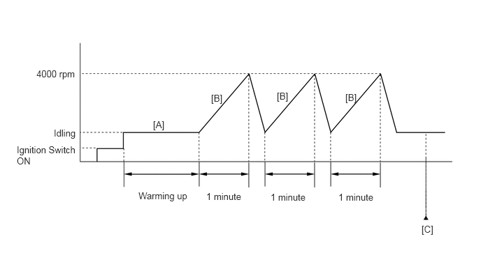
Connect the GTS to the DLC3.
Turn the ignition switch to ON.
Turn the GTS on.
Clear the DTCs (even if no DTCs are stored, perform the clear DTC procedure).
Turn the ignition switch off and wait for at least 30 seconds.
Turn the ignition switch to ON.
Turn the GTS on.
Start the engine and warm it up until the engine coolant temperature is 75°C (167°F) or higher with all the accessories switched off [A].
When the vehicle is stationery, gently depress the accelerator pedal until the engine speed increases to 4000 rpm for 1 minute, then release the accelerator pedal to return to the idling speed [B].
Repeat step [B] 3 times or more.
Enter the following menus: Powertrain / Engine / Trouble Codes [C].
Read the pending DTCs.
- HINT:
- ·
If a pending DTC is output, the system is malfunctioning.
·If a pending DTC is not output, perform the following procedure.
Enter the following menus: Powertrain / Engine / Utility / All Readiness.
Input the DTC: P052024 or P05202A.
Check the DTC judgment result.
| GTS Display | Description |
|---|---|
| NORMAL | ·
DTC judgment completed ·
System normal |
| ABNORMAL | ·
DTC judgment completed ·
System abnormal |
| INCOMPLETE | ·
DTC judgment not completed ·
Perform driving pattern after confirming DTC enabling conditions |
- HINT:
- ·
If the judgment result is NORMAL, the system is normal.
·If the judgment result is ABNORMAL, the system is malfunctioning.
·If the judgment result is INCOMPLETE, perform steps [B] through [C] again.
CAUTION / NOTICE / HINT
- HINT:
-
Read Freeze Frame Data using the GTS. The ECM records vehicle and driving condition information as Freeze Frame Data the moment a DTC is stored. When troubleshooting, Freeze Frame Data can help determine if the vehicle was moving or stationary, if the engine was warmed up or not, if the air fuel ratio was lean or rich, and other data from the time the malfunction occurred.
PROCEDURE
Connect the GTS to the DLC3.
Turn the ignition switch to ON.
Turn the GTS on.
Enter the following menus: Powertrain / Engine / Trouble Codes.
Read the DTCs.
- Powertrain > Engine > Trouble Codes
- 50001 372
- Result:
Result Proceed to DTC P052024 or P05202A is output A DTC P052024 or P05202A and other DTCs are output B
- HINT:
-
If any DTCs other than P052024 or P05202A are output, troubleshoot those DTCs first.
A
B
Read the value displayed on the GTS.
Connect the GTS to the DLC3.
Disconnect the oil pressure control valve assembly connector.
Start the engine.
Turn the GTS on.
Enter the following menus: Powertrain / Engine / Data List / Engine Speed, Engine Oil Temperature Sensor and Engine Oil Pressure.
- Powertrain > Engine > Data List
-
Tester Display Engine Speed Engine Oil Temperature Sensor Engine Oil Pressure - 50003 372 211,261,103
With the engine oil temperature at 75 to 85°C (167 to 185°F), read the "Engine Oil Pressure" with the engine speed at 2000 rpm.
Read the oil pressure using an oil pressure gauge with adapter.
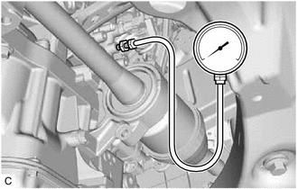
Install the oil pressure gauge with adapter.
Click hereEngine / Hybrid System>A25A-FKS (LUBRICATION)>OIL PRESSURE SENSOR>REMOVAL
- CAUTION:
-
Removing the oil pressure sender gauge assembly while the engine is hot could result in burns caused by contact with hot engine oil.
- NOTICE:
-
Clean the hose and adapter of the oil pressure gauge before and after measurement.
Start the engine.
With the engine oil temperature at 75 to 85°C (167 to 185°F), read the oil pressure gauge with the engine speed at 2000 rpm.
Compare the Data List value and the oil pressure gauge reading.
- OK:
Data List value and gauge reading are within +/-50 kPa (7.3 psi) of each other
- HINT:
-
Be sure to clear the DTCs after reinstalling the oil pressure sensor (oil pressure sender gauge assembly) or reconnecting the oil pressure sensor (oil pressure sender gauge assembly) or oil pressure control valve assembly connector, as DTCs may be stored.
- Result:
Proceed to OK NG
OK
NG