U761E AUTOMATIC TRANSMISSION / TRANSAXLE OIL COOLER INSTALLATION
PROCEDURE

 33493A
1.INSTALL TRANSMISSION OIL COOLER
Install the transmission oil cooler to the front engine mounting bracket with the 2 bolts.
- Torque:
- 13.5 N*m (138 kgf*cm, 10 ft.*lbf)
2.CONNECT NO. 1 TRANSMISSION OIL COOLER HOSE ASSEMBLY
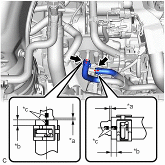
| *a | 0 to 3 mm (0 to 0.118 in.) |
| *b | 2 to 7 mm (0.0787 to 0.276 in.) |
| *c | Paint Mark |
Connect the No. 1 transmission oil cooler hose assembly to the transmission oil cooler and slide the 2 clips to secure it.
- NOTICE:
- ·
Make sure to slide the No. 1 transmission oil cooler hose assembly until it contacts the hose stopper of the transmission oil cooler.
·Make sure to align the paint mark of the No. 1 transmission oil cooler hose assembly with the paint mark of the transmission oil cooler.
16267K
3.CONNECT NO. 3 WATER BY-PASS HOSE
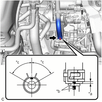
| *a | 2 to 7 mm (0.0787 to 0.276 in.) |
| *b | Paint Mark |
| *c | 60° (Claw of Clip Location) |
Connect the No. 3 water by-pass hose to the transmission oil cooler and slide the clip to secure it.
- NOTICE:
- ·
Make sure to slide the No. 3 water by-pass hose until it contacts the hose stopper of the transmission oil cooler.
·Make sure to align the paint mark of the No. 3 water by-pass hose with the paint mark of the transmission oil cooler.
·Make sure that the claws of the clip are within the location shown in the illustration.
16281N
4.CONNECT NO. 4 WATER BY-PASS HOSE
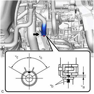
| *a | 2 to 7 mm (0.0787 to 0.276 in.) |
| *b | Paint Mark |
| *c | 60° (Claw of Clip Location) |
Connect the No. 4 water by-pass hose to the transmission oil cooler and slide the clip to secure it.
- NOTICE:
- ·
Make sure to slide the No. 4 water by-pass hose until it contacts the hose stopper of the transmission oil cooler.
·Make sure to align the paint mark of the No. 4 water by-pass hose with the paint mark of the transmission oil cooler.
·Make sure that the claws of the clip are within the location shown in the illustration.
17700
5.INSTALL AIR CLEANER ASSEMBLY
17750A
6.INSTALL INLET AIR CLEANER ASSEMBLY
53295E
7.INSTALL COOL AIR INTAKE DUCT SEAL
8.ADD ENGINE COOLANT
9.ADJUST AUTOMATIC TRANSAXLE FLUID
10.INSPECT FOR OIL LEAK
11.INSPECT FOR COOLANT LEAK