FRONT SUSPENSION FRONT LOWER SUSPENSION ARM(for 2AR-FE, 6AR-FSE LH Side) REMOVAL
CAUTION / NOTICE / HINT
The necessary procedures (adjustment, calibration, initialization, or registration) that must be performed after parts are removed and installed, or replaced during front lower No. 1 suspension arm sub-assembly LH removal/installation are shown below.
| Replaced Part or Performed Procedure | Necessary Procedure | Effect/Inoperative Function when Necessary Procedure not Performed | Link |
|---|---|---|---|
| Front wheel alignment adjustment | Perform system variant learning and acceleration sensor zero point calibration. | ·
VSC disabled or malfunctioning ·
DTCs are output ·
Slip indicator light illuminated ·
ABS warning light illuminated |
( ) |
| Suspension, tires, etc.
(The vehicle height changes because of suspension or tire replacement) |
Rear television camera assembly optical axis (Back camera position setting) | Parking assist monitor system | for Initialization:()
for Calibration:( )
|
·
Television camera controller initialization ·
Adjust steering angle ·
Rear television camera assembly optical axis (Back camera position setting) |
Panoramic view monitor system | for Initialization:()
for Calibration:( )
|
|
| Perform headlight ECU sub-assembly LH initialization | Lighting System (EXT) (w/ Automatic Headlight Beam Level Control System) | ()
|
PROCEDURE

 1.REMOVE FRONT WHEEL
53852K
2.REMOVE FRONT WHEEL OPENING EXTENSION PAD LH
for 2AR-FE: Click hereEngine / Hybrid System>2AR-FE (ENGINE MECHANICAL)>ENGINE ASSEMBLY>REMOVAL
for 6AR-FSE: Click hereEngine / Hybrid System>6AR-FSE (ENGINE MECHANICAL)>ENGINE ASSEMBLY>REMOVAL
53851M
3.REMOVE FRONT WHEEL OPENING EXTENSION PAD RH
for 2AR-FE: Click hereEngine / Hybrid System>2AR-FE (ENGINE MECHANICAL)>ENGINE ASSEMBLY>REMOVAL
for 6AR-FSE: Click hereEngine / Hybrid System>6AR-FSE (ENGINE MECHANICAL)>ENGINE ASSEMBLY>REMOVAL
51441
4.REMOVE NO. 1 ENGINE UNDER COVER
for 2AR-FE: Click hereEngine / Hybrid System>2AR-FE (ENGINE MECHANICAL)>ENGINE ASSEMBLY>REMOVAL
for 6AR-FSE: Click hereEngine / Hybrid System>6AR-FSE (ENGINE MECHANICAL)>ENGINE ASSEMBLY>REMOVAL
53737B
5.REMOVE FRONT FENDER APRON SEAL LH
for 2AR-FE: Click hereEngine / Hybrid System>2AR-FE (ENGINE MECHANICAL)>ENGINE ASSEMBLY>REMOVAL
for 6AR-FSE: Click hereEngine / Hybrid System>6AR-FSE (ENGINE MECHANICAL)>ENGINE ASSEMBLY>REMOVAL
17700
6.REMOVE AIR CLEANER ASSEMBLY
for 2AR-FE: Click hereEngine / Hybrid System>2AR-FE (ENGINE CONTROL)>ECM>REMOVAL
for 6AR-FSE: Click hereEngine / Hybrid System>6AR-FSE (ENGINE CONTROL)>ECM>REMOVAL
7.REMOVE BATTERY
for 2AR-FE: Click hereGeneral>MAINTENANCE>2AR-FE BATTERY>REMOVAL
for 6AR-FSE: Click hereGeneral>MAINTENANCE>6AR-FSE BATTERY>REMOVAL
74404A
8.REMOVE BATTERY CLAMP SUB-ASSEMBLY
48069
9.SEPARATE FRONT LOWER NO. 1 SUSPENSION ARM SUB-ASSEMBLY LH
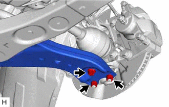
Remove the bolt and 2 nuts and separate the front lower No. 1 suspension arm sub-assembly LH from the front lower ball joint assembly LH.
12361A
10.SEPARATE FRONT ENGINE MOUNTING INSULATOR
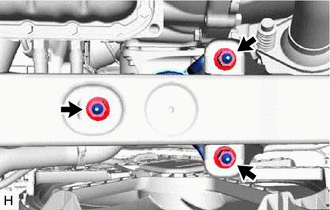
Remove the 3 nuts and separate the front engine mounting insulator from the front frame assembly.
48069
11.REMOVE FRONT LOWER NO. 1 SUSPENSION ARM SUB-ASSEMBLY LH
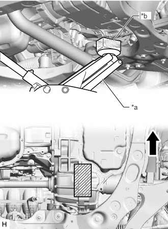
| *a | Jack |
| *b | Wooden Block |

|
Front of the Vehicle |

|
Wooden Block Placement Location |
Using a jack and wooden block, support the engine assembly with transaxle at the position shown in the illustration.
- NOTICE:
- ·
Do not position the wooden block under the oil pan.
·Ensure that the jack and wooden block are stable.
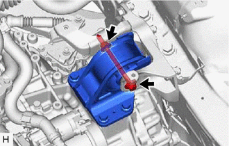
Remove the bolt and nut and separate the engine mounting insulator LH from the engine mounting bracket sub-assembly LH.
While ensuring that there is no interference from the components surrounding the engine, tilt the engine assembly with transaxle to a position that allows the front lower No. 1 suspension arm sub-assembly LH bolt.
- NOTICE:
- ·
Do not damage the components surrounding the engine assembly with transaxle.
·Tilt the engine assembly with transaxle as little as possible.
·Keep the engine assembly with transaxle supported until installation of the front lower No. 1 suspension arm sub-assembly LH.
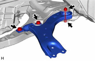
Remove the 3 bolts, nut and front lower No. 1 suspension arm sub-assembly LH from the front frame assembly.
- NOTICE:
-
Because the nut has its own stopper, do not turn the nut. Loosen the bolt with the nut secured.
Remove the front lower arm bushing stopper from the front lower No. 1 suspension arm sub-assembly LH.